A deceleration clutch bearing installation structure
A deceleration clutch and installation structure technology, applied in the field of washing machines, can solve the problems of high cost, large volume, unfavorable manufacturing and installation, etc., and achieve the effects of long service life, improved transmission efficiency and high reliability
- Summary
- Abstract
- Description
- Claims
- Application Information
AI Technical Summary
Problems solved by technology
Method used
Image
Examples
Embodiment 1
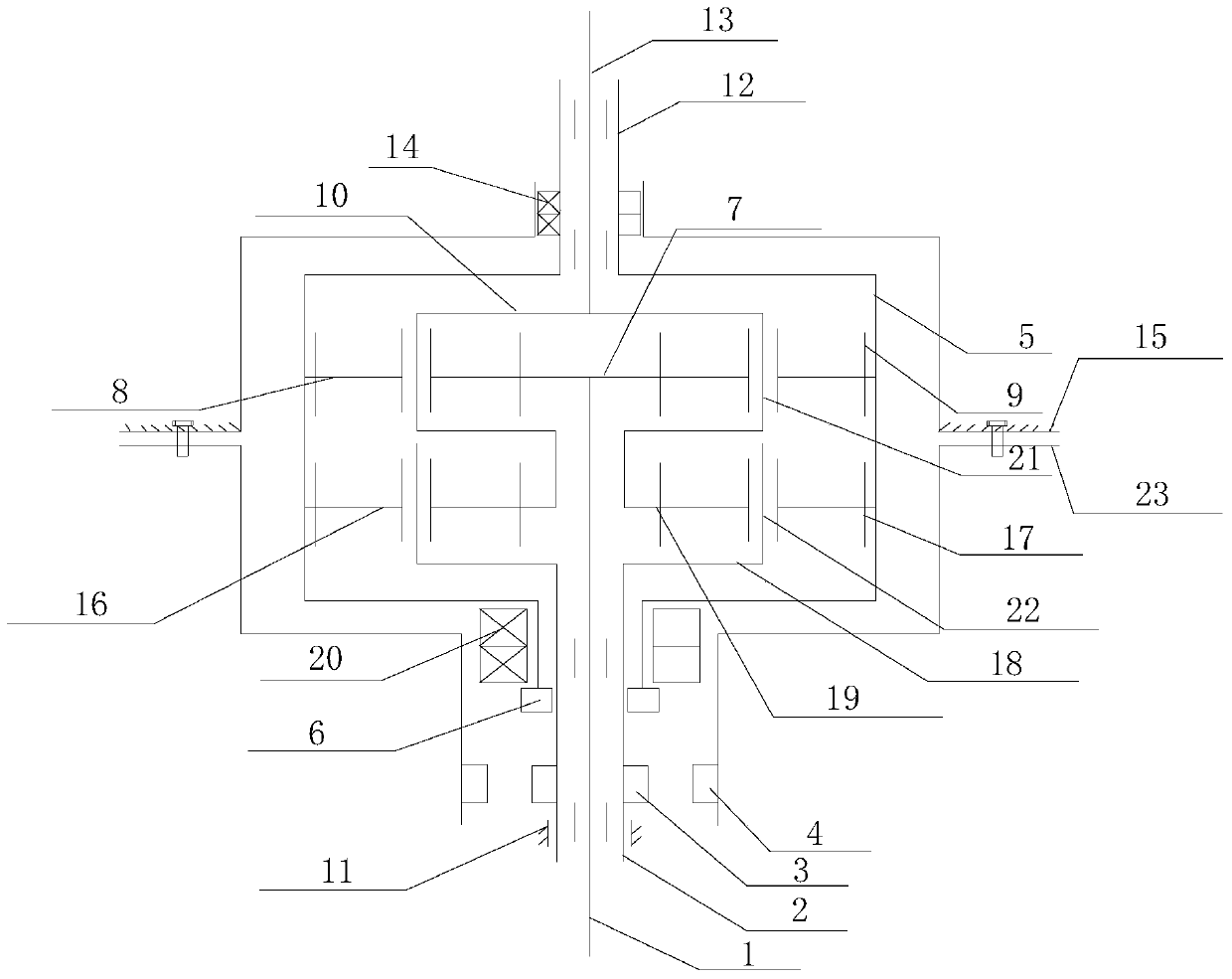
[0046] Such as figure 1 As shown, the clutch device described in this embodiment includes a dehydration pin 6 installed at the lower end of the wheel train housing 5, a clutch sleeve 3 installed at the input shaft sleeve 2 and rotating integrally with the input shaft sleeve 2, and a clutch sleeve installed at the lower end of the lower end cover 23. The brake pin 4 and the driving clutch sleeve 3 are respectively connected to / disconnected from the dehydration pin 6 and the brake pin 4;
[0047] In the washing state, the drive unit controls the clutch sleeve 3 to be connected to the brake pin 4 and to be disconnected from the dehydration pin 6 , and in the dehydration state, to control the clutch sleeve 3 to be connected to the dehydration pin 6 and to be disconnected from the brake pin 4 .
[0048] At least one first bearing 11 is arranged on the input shaft sleeve 2 of the present invention, specifically, no less than two first bearings 11 are encapsulated at the assembling p...
Embodiment 2
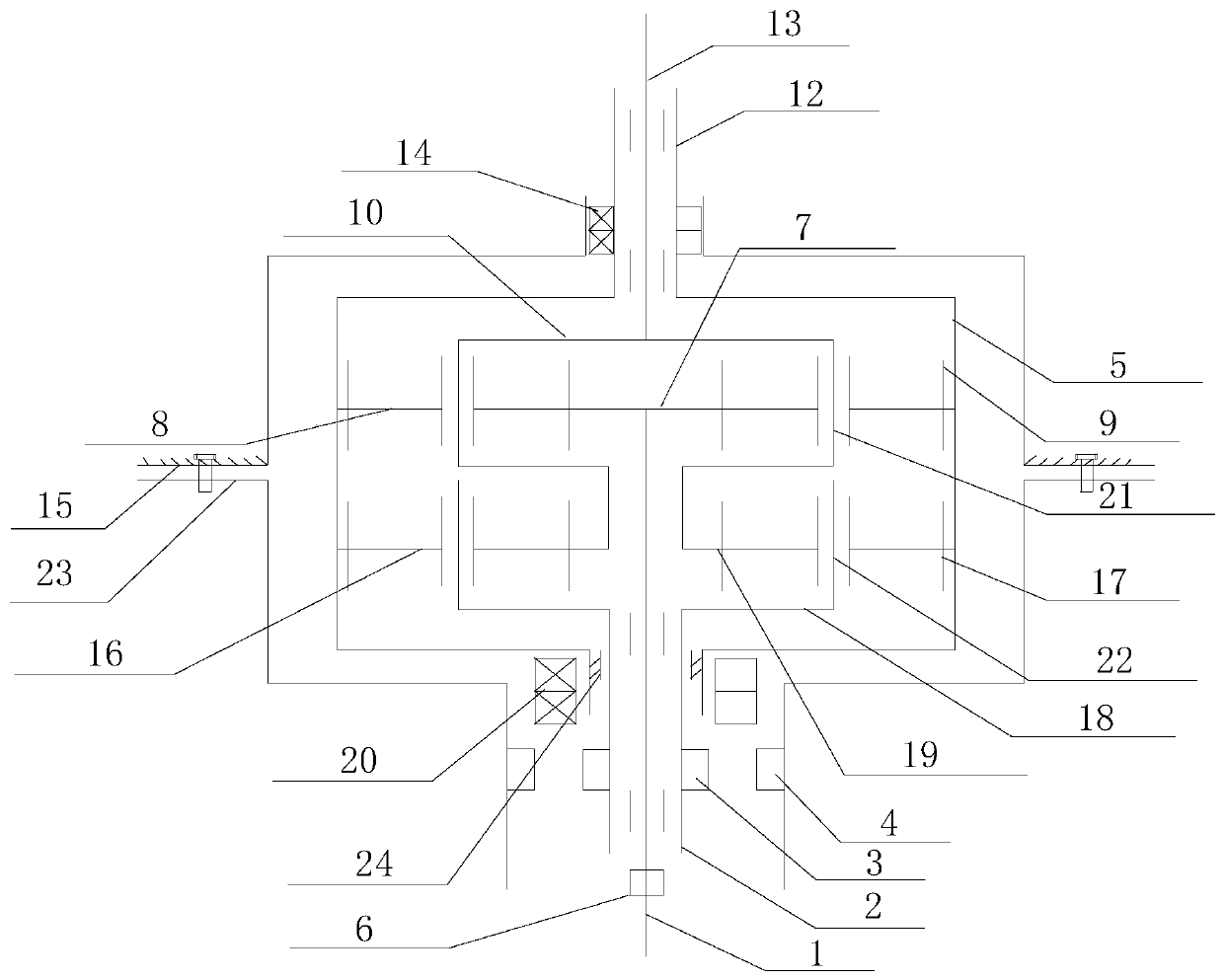
[0050] Such as figure 2 As shown, the clutch device described in this embodiment includes a dehydration pin 6 installed on the input shaft 1, a clutch sleeve 3 installed on the input shaft sleeve 2 and rotating integrally with the input shaft sleeve 2, and a braking device installed at the lower end of the lower end cover 23. Pin 4 and driving clutch sleeve 3 are respectively connected to / disconnected with dehydration pin 6 and brake pin 4;
[0051] In the washing state, the drive unit controls the clutch sleeve 3 to be connected to the brake pin 4 and to be disconnected from the dehydration pin 6 , and in the dehydration state, to control the clutch sleeve 3 to be connected to the dehydration pin 6 and to be disconnected from the brake pin 4 .
[0052] At least one fourth bearing 24 is arranged between the wheel train casing 5 and the input shaft sleeve 2 in the present invention. In the present invention, by providing more than one fourth bearing 24, the bearing support fu...
Embodiment 3
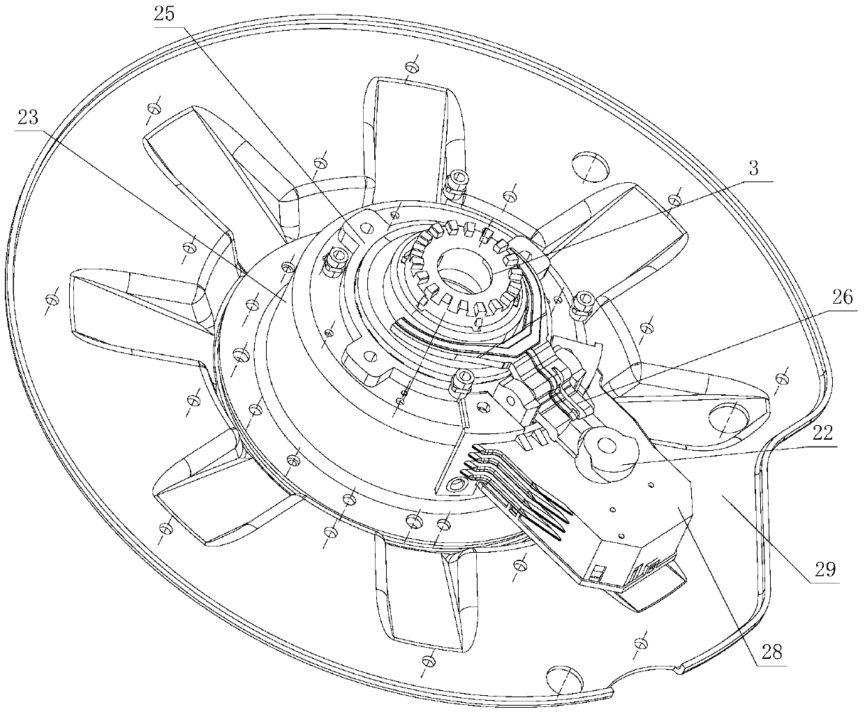
[0054] In the above embodiment, the clutch sleeve 3 is slidably installed on the input shaft sleeve 2 up and down, and rotates integrally with the input shaft sleeve 2; the clutch sleeve 3 is controlled by the drive unit to slide up and down to be splined with the dehydration pin 6 and the brake pin 4, When disconnected, the drive unit includes a return spring and a device to drive the action of the clutch sleeve. The device is electromagnetically driven or mechanically driven, such as a shift fork structure.
PUM
 Abstract
Description
Claims
Application Information
 - R&D
- Intellectual Property
- Life Sciences
- Materials
- Tech Scout
- Unparalleled Data Quality
- Higher Quality Content
- 60% Fewer Hallucinations
Browse by: Latest US Patents, China's latest patents, Technical Efficacy Thesaurus, Application Domain, Technology Topic, Popular Technical Reports.
© 2025 PatSnap. All rights reserved.Legal|Privacy policy|Modern Slavery Act Transparency Statement|Sitemap|About US| Contact US: help@patsnap.com


