
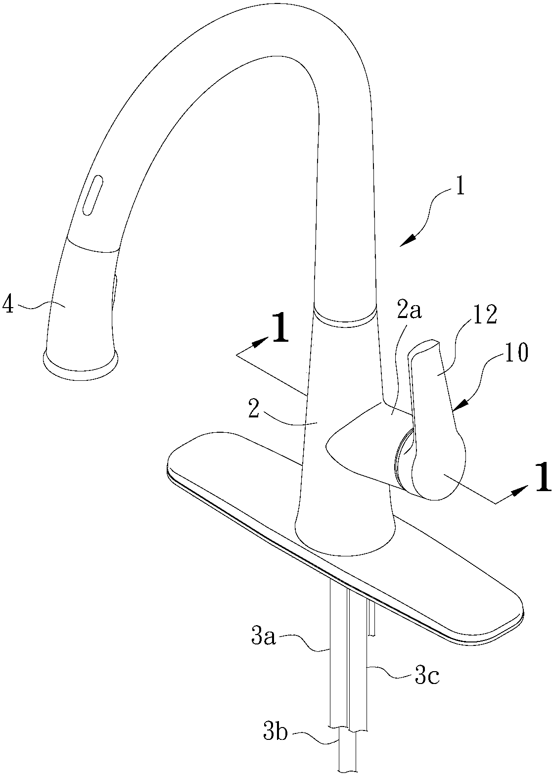
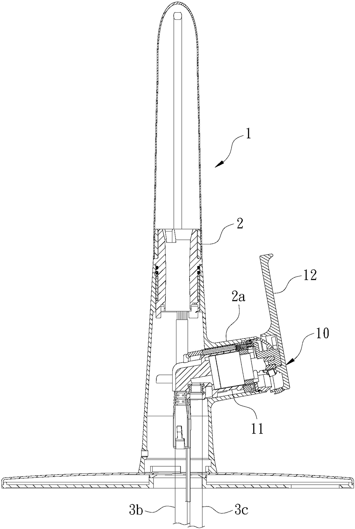
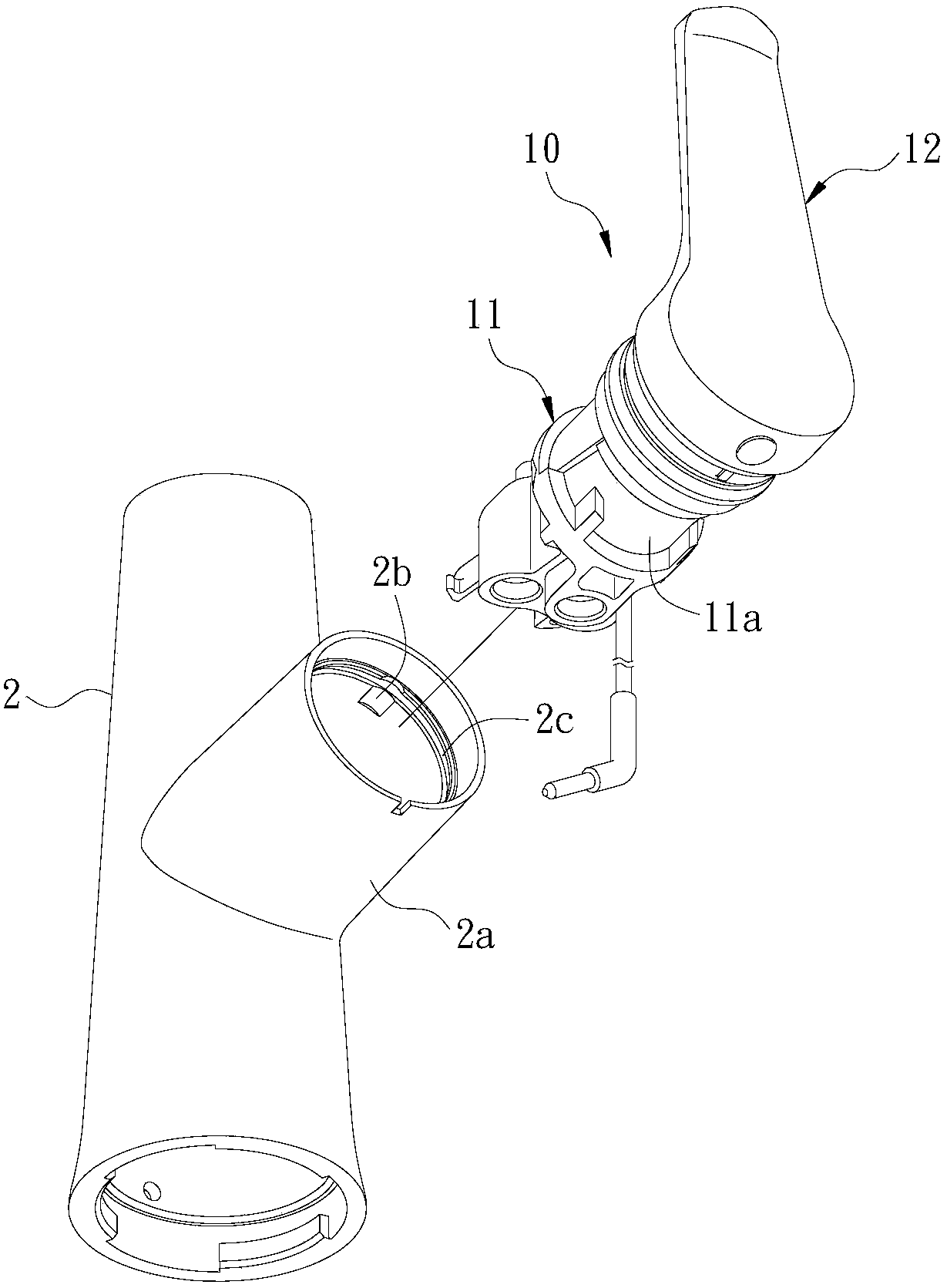
faucet structure

A faucet and structure technology, applied to valve details, multi-way valves, engine components, etc., can solve problems such as inaccurate alignment, bad, affecting assembly and subsequent use operation quality, etc., and achieve the effect of easy and fast disassembly and replacement

Inactive Publication Date: 2018-06-22
GLOBE UNION INDAL
View PDF8 Cites 0 Cited by
  • Summary
  • Abstract
  • Description
  • Claims
  • Application Information

AI Technical Summary

Problems solved by technology

[0005] Traditional ceramic spools or stainless steel spools are screw-locked with the inner peripheral wall of the valve seat of the faucet body by a lock ring, so as to resist and tighten the valve core, so that the valve assembly can be installed and locked on the valve seat of the faucet body However, due to the unavoidable processing errors in manufacturing, the lock ring is often found to be unable to be accurately positioned on the opposite wall of the valve core of the valve assembly during the screw locking process. At this time, usually the only way to increase the locking torque is to In order to alleviate the problem that the valve core and the valve housing of the valve assembly may not be effectively sealed, once the seal cannot be effectively sealed, it may cause leakage of cold, hot water or mixed water, resulting in problems such as inability to switch smoothly or poor water temperature control. Therefore, the locking torque The size control will affect the quality of assembly and subsequent use operations
[0006] The fixed structure of the traditional one-piece lock ring, because the lock ring is a screw that must be rotated, it is not suitable for installing any electronic control related components, such as the electronic control of water outlet and water shut-off by the handle switch operation Type switch device, but there must be a corresponding structural improvement, but also to ensure the installation stability and ease of assembly of the valve assembly

Method used


Image

  • faucet structure
  • faucet structure
  • faucet structure

Examples


no. 1 example

[0040] like Figures 1 to 6 As shown, the present invention provides a first embodiment of a faucet structure. The faucet can be an electronic faucet or a traditional manual switching faucet. This embodiment takes the electronic faucet 1 as an implementation form, and the electronic faucet 1 includes a control handle assembly 10. A switch device 20 and a touch element 30; wherein:

[0041] The control handle assembly 10 is installed on a faucet body 2 of the electronic faucet 1, and includes a valve assembly 11 and a handle 12. The valve assembly 11 can properly mix the inflowing cold and hot water to form mixed water and export it out. There is provided a first installation site 111 and a second installation site 112, such as Figure 7 As shown; the handle 12 is connected to the valve assembly 11, which can be pulled in and out between an open position and a closed position to switch and control the valve assembly 11, and be switched between a cold water position and a hot w...


PUM


Abstract

The invention provides a faucet structure, and particularly relates to a valve assembly fixing structure. The faucet structure mainly comprises a faucet body and a valve assembly. A positioning groove formed in the axial direction in a concave manner and a positioning annular groove formed in the circumferential direction in a concave manner are formed in the inner circumferential wall of a valve base of the faucet body. The valve assembly comprises a valve casing arranged inside the valve base, a valve element arranged in the valve casing, a fixed annular base, a buckling ring and an adjustment ring. A positioning protruding block is arranged on the outer circumferential wall of the fixed annular base in a protruding manner. The positioning protruding block and the positioning groove of the valve base are positioned in a mutual embedded and sliding manner so that the circumferential-direction rotation of the fixed annular base can be limited. The buckling ring and the positioning annular groove of the valve base are buckled so that the phenomenon that the fixed annular base disengages from and slides out of the valve base in the axial direction can be limited. The adjustment ring and the fixed annular base are locked in a screwed manner so that the valve element can be tightened and fixed in the axial direction. In this way, it can be ensured that the adjustment ring and the valve element are accurately aligned and firmly assembled, and therefore the valve assembly assembling quality can be improved, subsequent maintenance, disassembly, assembly and replacement of the valve element are facilitated, and an electronic control assembly can be conveniently assembled on the fixed annular base.

Description

technical field [0001] The invention relates to a faucet structure, in particular to a valve assembly fixing structure of the faucet. Background technique [0002] As we all know, the control handle of the traditional single-handle faucet usually adopts a typical ceramic valve core or stainless steel valve core, that is, there is a ceramic chip or stainless steel chip inside the valve core that can be rotated relatively to adjust the mixing flow. 、Turn the handle outward to control the water outlet and adjust the flow. For example, when you pull the handle outward, you can open and increase the water flow, and when you pull it back inward, you can close or reduce the water flow. In addition, when the handle is turned left or right, the output of cold water or hot water can be controlled, or the mixing ratio of cold water and hot water can be controlled to adjust the outlet water temperature. The new patent with the certificate number M318692 discloses a similar faucet, but ...

Claims


Application Information

Patent Timeline
Patent Type & Authority Patents(China)
IPC IPC(8): F16K11/02F16K11/14F16K31/06
CPCF16K11/02F16K11/14F16K31/0603F16K31/0675
Inventor 洪居万杨兆达郑忠义
Owner GLOBE UNION INDAL
Learn More