
superheater for boiler

A superheater and boiler technology, which is applied in the field of boilers, can solve the problems of increased length, reduced service life, and increased cost of superheater tubes, and achieves the effects of saving product costs, prolonging service life, and eliminating expansion constraints

Inactive Publication Date: 2017-04-05
郑向阳
View PDF6 Cites 0 Cited by
  • Summary
  • Abstract
  • Description
  • Claims
  • Application Information

AI Technical Summary

Problems solved by technology

Therefore, in order to support gravity direction loads such as the weight of headers and superheater pipes, it is usually necessary to set up variable force or constant force hangers, which are costly; or set non-zero clearance limit devices to support horizontal loads such as earthquakes and wind ; instead of a limit device with 0 clearance, because of the clearance, the superheater tube must bear additional load
If a rigid support device is used for the header perpendicular to the plane of the furnace wall, the superheater tubes will be subjected to additional stress, resulting in reduced service life or failure, or increasing the required length of the superheater tubes and increasing the cost. Cause unreasonable or wrong design

Method used


Image

  • superheater for boiler
  • superheater for boiler
  • superheater for boiler

Examples


Embodiment 1

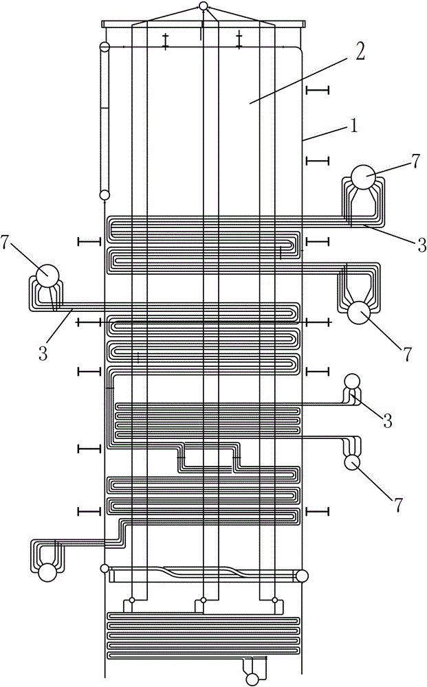
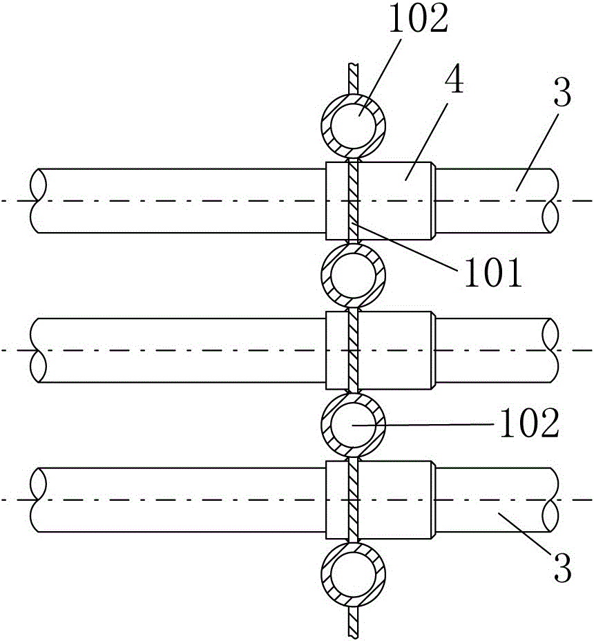
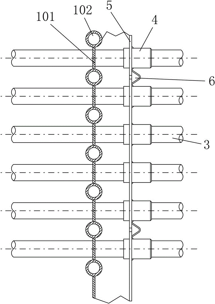
[0098] according to Figure 10~Figure 14 , the furnace wall 1 is a membrane wall, including furnace wall pipes 102 and fins 101 connected between the furnace wall pipes 102, and the wall penetration hole 10 includes several furnace wall pipes 102 directly adjacent to each other. Between the windows 1001, each window 1001 passes through several superheater tubes 3, in this embodiment, each window 1001 passes through three superheater tubes 3, the window The number of holes 1001 is determined by the number of superheater pipes 3, and one through-wall hole 10 is a unit. Between the window hole 1001 and the superheater pipe 3 is the expansion movement gap 11; the moving distance of the superheater pipe 3 during displacement is within the range of the expansion movement gap 11, that is to say, the superheater After the displacement, the pipe 3 is still located within the space accommodated by the expansion movement gap 11 without touching the hole wall of the window hole 1001 . T...

Embodiment 2

[0104] Different from Example 1, according to Figure 15 , the wall penetration hole 10 includes several window holes 1001, and the window holes 1001 are located on the fins 101; each window hole 1001 passes through one superheater tube 3, and the window holes 1001 and Between the superheater tubes 3 is the expansion movement gap 11 . The superheater pipe 3 is offset in the window 1001 to the opposite direction of the displacement path of the superheater pipe 3, such as Figure 15 , the displacement path of the superheater pipe 3 is to the right, then the superheater pipe 3 shifts to the left of the window hole 1001 in the cold state, and the displacement distance of the superheater pipe 3 is within the range of the expansion movement gap 11 Inside.

[0105] according to Figure 16 , the refractory component 12 includes several refractory units 1202, and the two side edges of the two adjacent refractory units 1202 are staggered back and forth to prevent the expansion differ...

Embodiment 3

[0108] Different from Example 1, according to Figure 17 , Figure 18 , Figure 19, the wall penetration hole 10 includes several windows 1001 between two furnace wall pipes 102, and the two furnace wall pipes 102 on both sides of the window hole 1001 can be non-adjacent furnace wall pipes. When another 1 or 2 furnace wall pipes, that is, the middle furnace wall pipe 103 are arranged between the 2 furnace wall pipes 102 on both sides of 1001, when the middle furnace wall pipe 103 passes through the window hole 1001 of the through-wall hole 10 , through partly bending in the direction of avoiding space collision with the displacement path of the superheater pipe 3 to form a curved section 1031, so as to reserve the window hole 1001 of the through-wall hole 10, so that the superheater pipe 3 can pass through the through-wall hole At 10 o'clock, there is no obstacle on the displacement path of the superheater pipe 3 . In this embodiment, each window hole 1001 traverses through...


PUM


Abstract

The invention relates to a superheater for a boiler. The boiler comprises a furnace chamber and a furnace wall, and the superheater comprises a superheater tube and a connecting box, wherein a wall-through hole is formed in the furnace wall, and an expanded moving gap is formed between the wall-through hole and the superheater tube; a refractory component is arranged on the superheater tube and positioned on one side of the wall-through hole, and a sealing box is arranged on the outer side of the furnace wall; the tube wall-through hole, the refractory component and the superheater tube are sealed between the sealing box and the furnace chamber, and the collecting box is positioned in the sealing box or one side, close to the furnace wall, of the collecting box is sealed in the sealing box; when the collecting box is positioned in the sealing box, a fixed guide device is arranged on the collecting box or a connecting pipeline. The superheater has the advantages that the superheater tube can be unrestricted on all expansion displacement paths, the length of the superheater tube is shortened, the cost of the superheater is greatly reduced, the stress level of the superheater is reduced, and the service life is prolonged.

Description

technical field [0001] The invention relates to a boiler, in particular discloses a superheater applied to the boiler. Background technique [0002] In the existing boiler structure, the superheater includes a header and a superheater tube; the header includes an inlet header and an outlet header, and its function is to distribute and collect steam before and after heat exchange in the superheater tube. The superheater tube of the superheater enters the furnace cavity directly from the outside of the boiler wall, and the connection between the furnace wall and the superheater is usually a fixed connection, that is, the superheater tube of the superheater is directly welded on the furnace wall of the boiler, and the superheater tube is connected to the boiler wall. The end connected to the furnace wall is constrained by the furnace wall and moves in the direction of expansion of the furnace wall, and the end of the superheater pipe connected to the header moves in the directi...

Claims


Application Information

Patent Timeline
Patent Type & Authority Patents(China)
IPC IPC(8): F22G1/00F22G3/00
Inventor 郑向阳
Owner 郑向阳
Learn More