Verification System and Verification Method of High Frequency Partial Discharge Detector

A partial discharge and detector technology, applied in the field of electric power engineering, can solve the problem that the test results cannot effectively and truly reflect the operation status of the transformer, the performance of the instrument and the test accuracy cannot be effectively guaranteed, and the performance of the high-frequency partial discharge detector cannot be regularly inspected and other problems to achieve accurate and reliable test results, solve performance verification problems, and be easy to implement

Active Publication Date: 2017-03-22
STATE GRID CORP OF CHINA +2
View PDF5 Cites 0 Cited by
  • Summary
  • Abstract
  • Description
  • Claims
  • Application Information

AI Technical Summary

Problems solved by technology

However, there is still a lack of effective and unified methods for the performance verification of high-frequency partial discharge sensors. As a result, regular testing of high-frequency partial discharge live detectors has not been carried out during use, and the performance and test accuracy of the instruments cannot be effectively guaranteed, resulting in field applications. The test results of different instruments are quite different, the reliability is not high, and the test results cannot effectively and truly reflect the operating status of electrical equipment such as transformers, cables and arresters
In order to solve the above problems, it is necessary to study an effective and unified high-frequency partial discharge detection sensor verification system and method to solve the problem that the performance of the high-frequency partial discharge detector (HFCT) cannot be regularly inspected and ensure the good performance of the instrument detection. In order to ensure that the detection results of the high-frequency partial discharge detector (HFCT) can accurately and effectively reflect the operating status of electrical equipment

Method used


Image

  • Verification System and Verification Method of High Frequency Partial Discharge Detector
  • Verification System and Verification Method of High Frequency Partial Discharge Detector
  • Verification System and Verification Method of High Frequency Partial Discharge Detector

Examples


Embodiment Construction

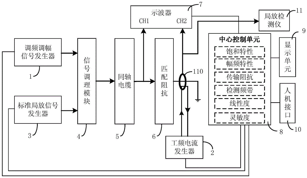
[0046] Such as figure 1 As shown, the verification system of the high-frequency partial discharge detector in this embodiment includes a frequency modulation and amplitude modulation signal generator 1, a power frequency current generator 2, a standard partial discharge signal generator 3, a signal conditioning module 4, a coaxial cable 5, and a matching impedance 6. The oscilloscope 7 and the central control unit 8, the output terminal of the FM and AM signal generator 1, and the output terminal of the standard partial discharge signal generator 3 are connected to the input terminal of the signal conditioning module 4 respectively, and the output terminal of the signal conditioning module 4 passes through the The coaxial cable 5 and the matching impedance 6 are grounded, and the high-frequency current sensor 110 of the verified high-frequency partial discharge detector 11 is set on the grounding cable of the matching impedance 6 and the output cable of the power frequency curr...


PUM


Abstract

The invention discloses a high-frequency partial discharge detector calibration system and a calibration method thereof. The system comprises a frequency modulation and amplitude modulation signal generator, a power-frequency current generator, a standard partial discharge signal generator, a signal conditioning module, a coaxial cable, a matching impedor, an oscilloscope, and a central control unit. The calibration method comprises the steps like calibrating the saturation characteristic of a high-frequency partial discharge detector. The amplitude and frequency of the frequency modulation and amplitude modulation signal generator are easy to adjust. The performance calibration requirement of high-frequency partial discharge detectors and high-frequency current sensors thereof can be satisfied. The problem on performance calibration of high-frequency partial discharge detectors and high-frequency current sensors thereof can be solved effectively and in a unified way. Regular inspection of high-frequency partial discharge detectors can be implemented easily. Good performance of high-frequency partial discharge detectors is ensured. The running status of electrical equipment can be reflected effectively. The system and the method of the invention have the advantages of accurate and reliable test results and easy implementation.

Description

technical field [0001] The invention relates to the technical field of electric power engineering, in particular to a high-frequency partial discharge detector verification system and a verification method thereof, which are used for performance verification of a high-frequency partial discharge detector (HFCT). Background technique [0002] With the rapid development of my country's economy, various industries have higher and higher requirements for the reliability and stability of power grid power supply, and the number of power outage tests for power equipment will also decrease accordingly. One of the primary means of status information. When partial discharge occurs in electrical equipment, a high-frequency pulse current with a frequency of 3MHz-30MHz will be generated, propagate along the metal parts of the electrical equipment, and enter the ground through the grounding wire. This signal can be detected by a high-frequency current sensor (HFCT) , the sensor can be use...

Claims


Application Information

Patent Timeline
Patent Type & Authority Patents(China)
IPC IPC(8): G01R35/00
Inventor 李欣叶会生段肖力段建家黄福勇周卫华
Owner STATE GRID CORP OF CHINA
Why Eureka
Try Eureka