Camera layout and calibration method for improving depth-of-field measurement precision

A calibration method and measurement accuracy technology, which can be used in image analysis, instruments, calculations, etc., can solve the problem of low measurement accuracy

Active Publication Date: 2016-01-06
DALIAN UNIV OF TECH
View PDF5 Cites 48 Cited by
  • Summary
  • Abstract
  • Description
  • Claims
  • Application Information

AI Technical Summary

Problems solved by technology

The camera layout method and depth-of-field calibration method proposed by the present invention are considered from two aspects of

Method used


Image

  • Camera layout and calibration method for improving depth-of-field measurement precision
  • Camera layout and calibration method for improving depth-of-field measurement precision
  • Camera layout and calibration method for improving depth-of-field measurement precision

Examples


Embodiment Construction

[0036] The specific embodiments of the present invention will be described in detail below in conjunction with the technical solutions and accompanying drawings.

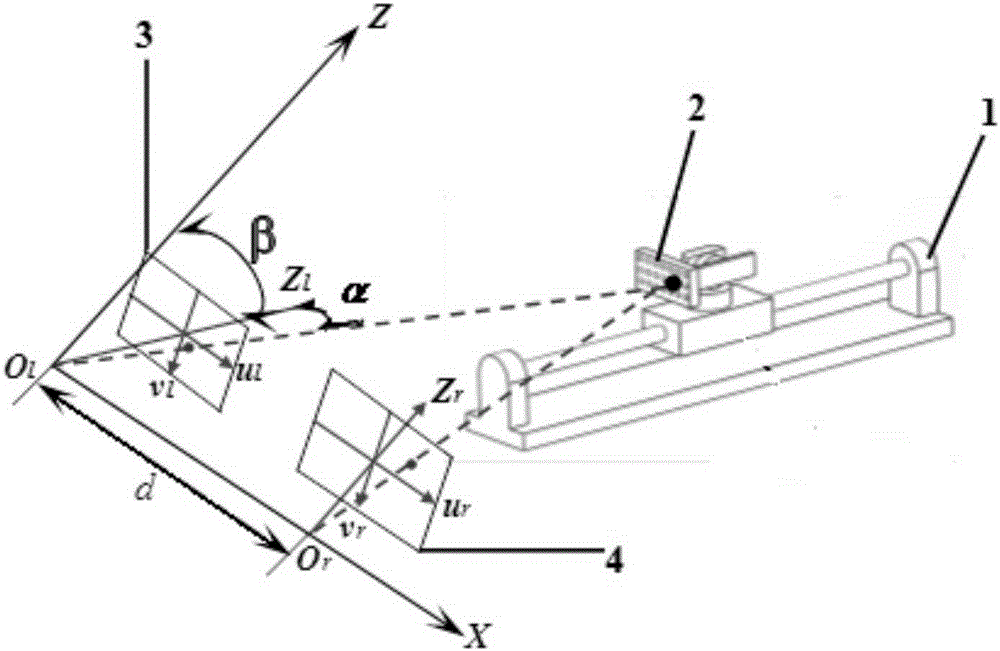
[0037] attached figure 1 Camera layout and calibration system diagram for improving depth of field measurement accuracy. The embodiment selects Zhuoli Hanguang high-precision electronic control device 1. The high-precision electronic control device 1 of the present invention can realize linear motion in one direction, with a linear stroke of 500mm, 360° rotation around the horizontal axis, and 360° around the vertical axis. rotate. The size of the high-precision two-dimensional plane calibration plate 2 used in the calibration process is 300mm×400mm, and the characteristic mark points on the calibration plate 2 are circular mark points, and the diameter of the circular mark points is 30mm, a total of 30, of which the calibration plate 2 Arrange 6 horizontally and 5 vertically. The selected left and right cameras 3 ...


PUM


Abstract

A camera layout and calibration method for improving the depth-of-field measurement precision of the invention belongs to the field of computer vision, and relates to a camera layout and depth-of-field calibration method for improving the measurement precision of cameras in the depth-of-field direction. The calibration method starts from both optimized camera layout and depth-of-field calibration, and improves the measurement precision of a vision measurement system in the depth-of-field direction. First, the baseline length and the angle between the optical axes of two cameras are determined to optimize camera layout; then, the scope of depth of field is determined according to the measurement object distance, the focusing state and the lens parameters, a calibration plate is driven by a high-precision electric control device to move between multiple positions in the depth-of-field direction of the camera, and the parameters of the binocular camera are calibrated by using multiple images of the calibration plate in each position; and during measurement, different camera parameters are selected in different positions of depth of field according to feature information to reconstruct feature 3D information. According to the invention, no prediction of the distortion model of any space in the depth of field is needed during calibration, and the robustness of calibration is improved. The calibration method has the advantages of simple process, high precision, and easy implementation.

Description

technical field [0001] The invention belongs to the field of computer vision measurement, and relates to a camera layout and calibration method for improving the accuracy of depth of field measurement. Background technique [0002] Space three-dimensional measurement is an important technical means to ensure the final quality of products. The continuous development of major national engineering fields such as aerospace, ships, and automobiles has put forward higher requirements for measurement. The structure of the measured object is complex, the measured parameters are many, the size and the range of motion are extended in three dimensions of space, and the measurement range is large. Visual measurement technology has the advantages of non-contact, high precision, strong real-time performance and adaptability, and wide measurement range, and has been widely used in high-precision measurement in recent years. Camera installation and calibration are very important and direct...

Claims


Application Information

Patent Timeline
IPC IPC(8): G06T7/00
Inventor 王福吉陈晨贾振元张博宇殷俊伟
Owner DALIAN UNIV OF TECH
Why Eureka
Try Eureka