Solar battery panel bearing mechanism based on crank rocking bar expansion structure

A solar panel and crank rocker technology, which is applied in the field of solar power generation, can solve problems such as the difficulty in effectively utilizing solar energy and panels, the limited number, and the single installation form of solar panels, so as to achieve convenient direction change, rapid deployment and retraction. The effect of meeting the power supply demand

Inactive Publication Date: 2016-01-06
HEILONGJIANG XINGAN NEW ENERGY
View PDF8 Cites 3 Cited by
  • Summary
  • Abstract
  • Description
  • Claims
  • Application Information

AI Technical Summary

Problems solved by technology

[0004] The purpose of the present invention is to solve the problem that the existing solar mobile power station has a single arrangement of solar panels and a limited number, and wh

Method used


Image

  • Solar battery panel bearing mechanism based on crank rocking bar expansion structure
  • Solar battery panel bearing mechanism based on crank rocking bar expansion structure
  • Solar battery panel bearing mechanism based on crank rocking bar expansion structure

Examples


specific Embodiment approach 1

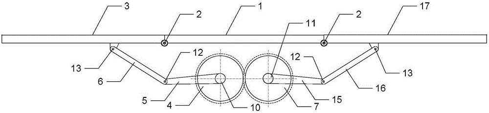
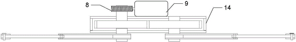
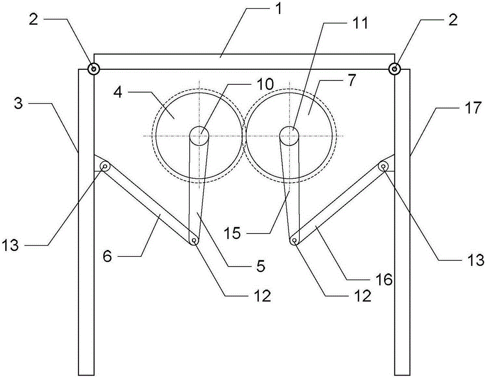
[0011] Specific implementation mode 1: the following combination Figure 1-Figure 3 To explain this embodiment, the solar panel carrying mechanism based on the crank and rocker deployment structure in this embodiment includes a battery panel support 1, a support shaft 2, a first battery panel side plate 3, a driving gear 4, and a driving wheel drive. Support arm 5, driving wheel driven arm 6, driven gear 7, worm gear 8, drive motor 9, driving gear shaft 10, driven gear shaft 11, driving arm coupling 12, side plate coupling 13, gear Box 14, driven wheel driving arm 15, driven wheel driven arm 16, and second battery plate side plate 17;

[0012] The driving motor 9 drives the worm gear 8 to rotate. The gear of the worm gear 8 meshes with the driving gear 4, and the driving gear 4 rotates along the driving gear shaft 10; the driving gear 4 drives the driving wheel driving arm 5, and the driving wheel driving arm 5 pushes the driving wheel The driven arm 6 rotates with the driving a...

specific Embodiment approach 2

[0013] Specific implementation manner 2: the following combination figure 1 To illustrate this embodiment, this embodiment will further explain the first embodiment, the driving gear 4 rotates in a clockwise direction along the driving gear shaft 10.

specific Embodiment approach 3

[0014] Specific implementation manner three: the following combination figure 1 This embodiment will be described. This embodiment will further explain the second embodiment. The driven gear 7 rotates in a counterclockwise direction along the driven gear shaft 11.


PUM


Abstract

The invention discloses a solar battery panel bearing mechanism based on a crank rocking bar expansion structure, belonging to the solar energy generation field. The invention solves the problems that the arrangement mode of the battery panel of the solar energy mobile power generation station is single and the number is limited, and when the sun light irradiation direction and intensity change, the solar energy and the battery panel are difficult to utilize. In the invention, a driving motor drives a worm gear and a worm to rotate; the gears of the worm gear and the worm are meshed with an active gear; the active gear drives an active wheel active support arm to rotate around a connection shaft of the active support art which is taken as an axis ; an active wheel slave support arm pushes a first battery panel side plate to rotate around a support which is taken as an axis, so that a first battery panel side plate is expanded; the slave gear is meshed with the active gear, which drives a slave wheel active support arm to rotate around the active support arm connection shaft which is taken as an axis; a slave wheel slave support pushes a second battery panel side plate to rotate around a support shaft which is taken as an axis through the side plate connection shaft, so that the second battery panel is expanded; and the gear box changes a transmission way and decelerates the driving motor. The invention is used for solar energy power generation.

Description

Technical field [0001] The invention relates to a solar cell panel carrying mechanism based on a crank and rocker deployment structure, which belongs to the field of solar power generation. Background technique [0002] In the process of power transmission, it is very important to ensure the smooth flow of transmission lines. As emergencies are mostly unforeseeable, and the emergency repair environment is mostly in areas with complex terrain, large-scale power outages or no electricity in the field, lighting on the emergency repair site is required to ensure the smooth implementation of the emergency repair work. The main function of the solar emergency protection power station is to provide power, lighting and life electricity for rescue and disaster relief, forest fire fighting, military activities and field operations, and can be used as important national institutions, large public places, hospitals, schools, newsletters The unit’s own power supply. It has functions such as...

Claims


Application Information

Patent Timeline
IPC IPC(8): H02S20/32H02S30/20
CPCY02E10/50
Inventor 于丰泽陈怀春于占江
Owner HEILONGJIANG XINGAN NEW ENERGY
Why Eureka
Try Eureka