
Two-position three-way reversing valve

A two-position three-way, reversing valve technology, applied in the direction of fluid pressure actuators, servo meter circuits, servo motor components, etc., can solve the problems of low working pressure, small flow control, cumbersome reversing, etc., and achieve simple structure Reasonable, simple reversing method, stable working pressure and flow rate

Pending Publication Date: 2021-03-16
鑫矿液压科技有限公司
View PDF0 Cites 0 Cited by
  • Summary
  • Abstract
  • Description
  • Claims
  • Application Information

AI Technical Summary

Problems solved by technology

Most of these driving methods are limited by the power of the conversion device, so that the working pressure is low, the control flow is small, it is difficult to meet the requirements of the control system, and the commutation is more cumbersome.

Method used


Image

  • Two-position three-way reversing valve
  • Two-position three-way reversing valve

Examples


Embodiment Construction

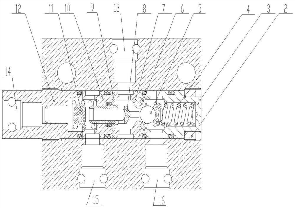
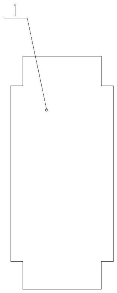
[0021] A two-position three-way reversing valve as shown in the accompanying drawings includes a valve body 1 and a positioning sleeve 12 arranged in the valve body 1. One end of the positioning sleeve 12 is provided with a control port 14, and one end of the control port 14 is provided with There is a valve stem assembly 11, one end of the valve stem assembly 11 is provided with a spool 8 cooperating with it, the valve body 1 is also provided with a middle valve sleeve 7, and one side of the middle valve sleeve 7 is provided with a valve seat 6, And the valve seat 6 is provided with a limit opening, and the limit opening is provided with a limit device that can be pushed back by the spool 8 .

[0022] Wherein, the middle and lower part of one end of the positioning sleeve 12 is provided with a protruding part, and the port of the other end is provided with a concave part, and the concave part is provided with an end sleeve 3 and a compression screw 2 for fastening the end slee...


PUM


Abstract

The invention discloses a two-position three-way reversing valve which comprises a valve body and a positioning sleeve arranged in the valve body. A control opening is formed in one end of the positioning sleeve; a valve rod assembly is arranged at one end of the control opening; a valve column matched with the valve rod assembly in action is arranged at one end of the valve rod assembly; a middlevalve sleeve is further arranged in the valve body; a valve seat is arranged on one side of the middle valve sleeve; a limiting opening is formed in the valve seat; and a steel ball capable of beingjacked open by the valve column is arranged in the limiting opening. The two-position three-way reversing valve provided by the invention is simple and reasonable in structure, reversing is achieved in a hydraulic mode, the reversing mode is simple and convenient, meanwhile, working pressure and flow are stable, and the requirements of a control system are easily met.

Description

technical field [0001] The invention belongs to the technical field of hydraulic equipment control, and in particular relates to a two-position three-way reversing valve. Background technique [0002] A hydraulic reversing valve is a directional control valve that controls fluid pressure to push a spool to change the direction of fluid flow. The current spool push methods mainly include manual, electromagnetic and so on. Most of these driving methods are limited by the power of the conversion device, so that the working pressure is low, the control flow is small, it is difficult to meet the requirements of the control system, and the commutation is more cumbersome. Contents of the invention [0003] (1) Technical problems to be solved [0004] In order to solve the above problems, the present invention proposes a two-position three-way reversing valve with simple reversing and stable flow. [0005] (2) Technical solution [0006] A two-position three-way reversing valv...

Claims


Application Information

Patent Timeline
Patent Type & Authority Applications(China)
IPC IPC(8): F15B13/02
CPCF15B13/02F15B2211/30525
Inventor 何志友南海静胡润民
Owner 鑫矿液压科技有限公司
Learn More