Series arrangement of hydraulic chain tensioner and ratchet

A technology of hydraulic tensioner and tensioner, which is applied in the direction of belt/chain/gear, transmission device, mechanical equipment, etc., which can solve the problems of efficiency and system durability, reduce chain preload, etc.

Inactive Publication Date: 2016-01-06
BORG WAMER CORP
View PDF9 Cites 3 Cited by
  • Summary
  • Abstract
  • Description
  • Claims
  • Application Information

AI Technical Summary

Problems solved by technology

In conventional tensioners, chain tensioning increases compression spring length and reduces chain preload, thereby requiring excess preload to compensate under new chain conditions, which has an adverse effect on efficiency and system durability

Method used


Image

  • Series arrangement of hydraulic chain tensioner and ratchet

Examples


Embodiment Construction

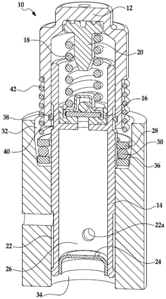
[0011] refer to figure 1 , the tensioner 10 for an annular power transmission member may include a piston 12 operatively engaged with the annular power transmission member and a cylinder 14 assembly, the piston 12 being operatively engaged with the annular power transmission member, and the cylinder 14 guiding the piston 12 to perform simultaneous motion in the direction of the annular power transmission member. The shaft slides and defines a reservoir 26 for receiving hydraulic fluid. Bearing 28 may have bearing balls 30 located in counterbore 32 coaxial with cylinder bore 34 . The counterbore 32 may have a steep taper 36 on which the bearing ball 30 rides, such that when the cylinder 14 moves in the extension direction, the bearing ball 30 moves out of the counterbore 32 to allow free extensional movement of the cylinder 14 and such that when the cylinder As the cylinder 14 moves in the retracting direction, the bearing balls 30 are driven downward into the steep cone 36 to...


PUM


Abstract

A tensioner (10) for an endless loop power transmission member can include a piston (12) operably engageable with an endless loop power transmission member, and a cylinder (14) guiding the piston (12) for sliding coaxial movement in a direction of the endless loop power transmission member. The piston (12) and cylinder (14) defining an oil reservoir or pressure chamber (26) for receiving hydraulic fluid. A bearing (28) has bearing balls (30) located in a counter bore (32) coaxial with cylinder bore (34). The counter bore (32) has a steep taper (36) on which the bearing balls (30) ride. As the cylinder (14) moves in an extending direction, the bearing balls (30) move out of the counter bore (32) allowing free extending movement of the cylinder (14). As the cylinder (14) moves in a retracting direction, the bearing balls (30) are driven down into the steep taper (36) preventing the cylinder (14) from retracting.

Description

technical field [0001] The present invention relates to a tensioner, and more particularly to an annular power transmission member tensioner for use in an endless power transmission drive of an internal combustion engine for tensioning the annular power transmission member during operation. Background technique [0002] Timed drive tensioners are designed to control the timed drive dynamic input transmitted through the chain and ultimately through the tensioner arm / face. To achieve this control, the tensioner is "tuned" either mechanically, hydraulically, or a combination of both. As the chain wears, the typical tensioner piston is designed to extend to take up the chain slack. Piston extension reduces mechanical bias spring force and can increase hydraulic leakage changing tensioner tuning. Such a change in tuning during the life cycle of the tensioner may be compensated by over tensioning of the tensioner when the tensioner initially compensates for piston extension duri...

Claims


Application Information

Patent Timeline
IPC IPC(8): F16H7/18F16H7/22
CPCF16H7/0836F16H7/0848F16H2007/0806F16H2007/0812F16H2007/0817F16H2007/0851F16H2007/0853
Inventor M·M·威格斯滕D·N·史密斯
Owner BORG WAMER CORP
Why Eureka
Try Eureka