Rotary knob type needle locking head

A knob-type and pin-lock technology, which is applied in the direction of sliding fastener components, applications, fasteners, etc., can solve the problem that the self-locking and unlocking of the slider cannot be realized, the convenience of using the slider is affected, and the braking effect of the horse hook is affected, etc. problems, to achieve the effect of simple structure, satisfying diverse needs, and novel and unique shapes

Active Publication Date: 2016-01-13
晋江市金圣拉链科技有限公司
View PDF6 Cites 8 Cited by
  • Summary
  • Abstract
  • Description
  • Claims
  • Application Information

AI Technical Summary

Problems solved by technology

[0004] In the use of this kind of rotary slider, the cap is threaded on the threaded column. Usually, the cap needs to be turned several times to completely lift the horse hook from the zipper. Similarly, when braking, the cap needs to be turned It takes multiple turns to make the horse hook stably embedded between the chain teeth of the zipper, so the operation is relatively time-consuming
At the same time, by setting the fixing part, the self-locking and unlocking of the slider cannot be realized without removing the locking of the fixing part. This setting will affect the convenience of the entire slider.
Furthermore, since the hook is set separately in this solution, the hook may rotate or deviate from the axis of the hook during use, which affects the braking effect of the hook

Method used


Image

  • Rotary knob type needle locking head
  • Rotary knob type needle locking head
  • Rotary knob type needle locking head

Examples


Embodiment Construction

[0040] In order to further explain the technical solution of the present invention, it will be described in detail below in conjunction with the accompanying drawings.

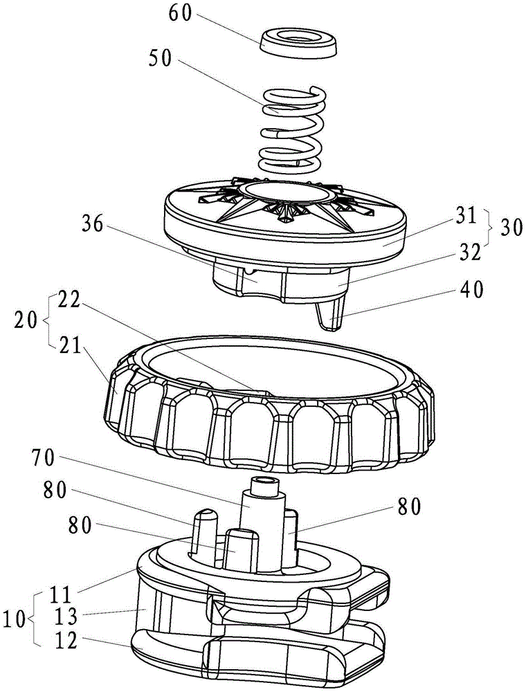
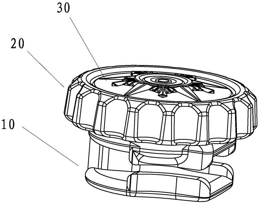
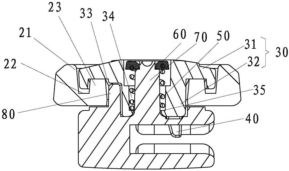
[0041] refer to Figure 1 to Figure 10, a knob-type needle lock head, including a slider body 10, a lock pin 40 and a rotating member 20, the slider body 10 includes an upper wing 11, a lower wing 12, and a connection between the upper wing 11 and the lower wing 12. Between the connecting column 13, the upper wing plate 11, the lower wing plate 12 and the connecting column 13 jointly form a guide chamber for guiding the zipper (not shown in the figure), and the upper wing plate 11 is provided with a locking pin 40 Through the through hole, the through hole runs through to the guide chamber, and the lock pin 40 is inserted between the chain teeth of the zipper through the through hole to brake the zipper. A guide column 70 is arranged on the upper wing plate 11 , one end of the guide column 70 is a fixed end f...


PUM


Abstract

The invention relates to a rotary knob type needle locking head which comprises a pull head body, a moving part, a spring and a rotating part. The pull head body comprises an upper wing plate, a lower wing plate and a connecting column, wherein a guide column is arranged on the upper wing plate. The rotary knob type needle locking head further comprises the moving part capable of moving in the axial direction of the guide column, wherein a locking needle is arranged on the moving part, the guide column is sleeved with the moving part, the moving part is sleeved with the rotating part, a limiting portion is arranged on the guide column, and an elastic part is arranged between the limiting portion and the moving part. The rotary knob type needle locking head further comprises a control mechanism for driving the moving part to lift and move, wherein the control mechanism is composed of sunken portions and protruding portions which are matched mutually. Therefore, unlocking of a zipper can be achieved only through small-angle rotation, and operation is very quick and convenient. After the protruding portions break away from the sunken portions, the locking needle is always located at the position breaking away from the zipper, and smooth and stable sliding of a pull head on the zipper can be ensured. When the pull head slides to a predetermined position, the rotating part is turned again to enable the protruding portions to fall into the sunken portions, the moving part returns under the effect of the elastic part, and the locking needle achieves zipper braking.

Description

technical field [0001] The invention belongs to the technical field of sliders, and in particular relates to a knob type needle lock head. Background technique [0002] Sliders and zippers are widely used in daily life. Traditional self-locking sliders generally include a slider body, a horse hook, elastic parts, a cap and a pull tab. When using the pull tab, the pull tab overcomes the tension of the elastic part. The elastic force lifts the hook from the chain teeth of the zipper to unlock the zipper. After the slider slides to the predetermined position on the zipper, release the pull piece, and the hook returns to its position under the action of the elastic part to realize the unlocking of the zipper. brake. With this structure, during the sliding process of the slider, the user always needs to exert a certain force on the hook through the pull tab to make the hook completely leave the zipper teeth. If the hook does not leave the zipper teeth, the slider will slide on t...

Claims


Application Information

Patent Timeline
Patent Type & Authority Applications(China)
IPC IPC(8): A44B19/30
Inventor 许荣批
Owner 晋江市金圣拉链科技有限公司
Why Eureka
Try Eureka