Waterproof light-oxygen catalyzing deodorizing type waste gas treatment device

An exhaust gas treatment device and technology of photo-oxygen catalysis, which are applied in chemical instruments and methods, dispersed particle separation, and use of liquid separation agents, etc., can solve the problem that the purification requirements of organic waste gas cannot be met, the air outlet has no rain shielding device, and the rain shielding device is self-contained. major problems, to achieve rapid and efficient decomposition, improve purification efficiency, and low cost

Inactive Publication Date: 2016-01-13
SUZHOU RHYMEBLUE ENVIRONMENTAL TECH CO
View PDF7 Cites 2 Cited by
  • Summary
  • Abstract
  • Description
  • Claims
  • Application Information

AI Technical Summary

Problems solved by technology

[0002] At present, there are more and more types of exhaust gas purification equipment. With the continuous development of industry, traditional exhaust gas purification processes such as: water absorption method, liquid absorption method, activated carbon absorption method, photochemical method or catalytic oxidation method can no longer meet the needs of current organic waste gas. purification needs
Most of the current exhaust gas purification equipment uses physical methods or chemical methods alone to treat exhaust gas. Physical methods can only remove particulate matter in exhaust gas, and chemical methods can only decompose organic matter in exhaust gas. , a device for efficiently treating particulate matter and organic matter in exhaust gas
In addition, the air outlet of the current exhaust gas purification equipment generally does not have a rain-shielding device, which causes the fan to easily enter water and malfunction
Even if a small number of exhaust gas purification equipment is equipped with rain-shielding devices, there are still problems such as the rain-shielding device is heavy, needs to be in contact with the ground, uses a lot of support materials, and occupies a large area.

Method used


Image

  • Waterproof light-oxygen catalyzing deodorizing type waste gas treatment device

Examples


Embodiment Construction

[0019] The present invention will be further described below in conjunction with the accompanying drawings.

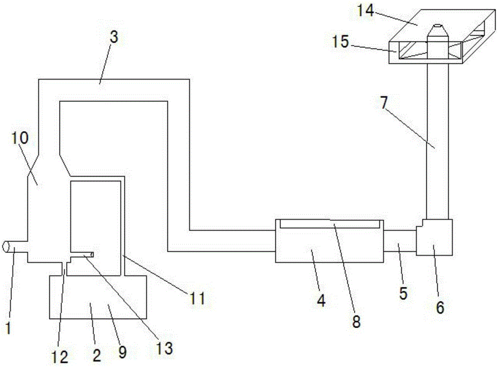
[0020] Such as figure 1 As shown, a waterproof photo-oxygen catalytic deodorization exhaust gas treatment device is characterized in that it includes: a spray unit 2 connected to the smoke inlet 1, and the top of the spray unit 2 passes through the first air channel 3 and The air inlet of photo-oxygen catalytic deodorization unit 4 links to each other, and the air outlet of described photo-oxygen catalytic deodorization unit 4 links to each other with the air inlet of blower fan 6 through the second airway 5, and the air outlet of described blower fan 6 is connected with vertical direction The third airway 7 is connected; the photo-oxygen catalytic deodorization unit 4 includes a housing and a high-energy electron generator 8 arranged in the housing, and a catalyst mesh plate and an ultraviolet lamp are also arranged in the housing; the light The oxygen catalytic deod...


PUM


Abstract

The invention discloses a waterproof light-oxygen catalyzing deodorizing type waste gas treatment device. The waterproof waste gas treatment device is characterized by comprising a spraying unit (2) connected with a smoke inlet (1), wherein the top end of the spraying unit (2) is connected with an air inlet of a light-oxygen catalyzing deodorizing unit (4) by a first air duct (3); an air outlet of the light-oxygen catalyzing deodorizing unit (4) is connected with an air inlet of a fan (6) by a second air duct (5); an air outlet of the fan (6) is connected with a vertical third air duct (7); and a rain shielding plate (14) is arranged at the top end of an air outlet of the third air duct (7) and is formed in a manner that a light bracket (15) is fixed on the side wall of the third air duct (7). The waterproof light-oxygen catalyzing deodorizing type waste gas treatment device provided by the invention has a rain shielding function to protect the fan from water entering, the rain shielding plate is fixed on the side wall of the third air duct, grounded surface support is not required, the self weight is light, materials are saved, and the cost is low.

Description

technical field [0001] The invention relates to a waste gas treatment device for waterproof photo-oxygen catalytic deodorization, belonging to the technical field of waste gas purification. Background technique [0002] At present, there are more and more types of exhaust gas purification equipment. With the continuous development of industry, traditional exhaust gas purification processes such as: water absorption method, liquid absorption method, activated carbon absorption method, photochemical method or catalytic oxidation method can no longer meet the needs of current organic waste gas. Purification needs. Most of the current exhaust gas purification equipment uses physical methods or chemical methods alone to treat exhaust gas. Physical methods can only remove particulate matter in exhaust gas, and chemical methods can only decompose organic matter in exhaust gas. , a device for efficiently treating particulate matter and organic matter in exhaust gas. In addition, t...

Claims


Application Information

Patent Timeline
Patent Type & Authority Applications(China)
IPC IPC(8): B01D53/86B01D47/06B01D53/44B01D53/76
Inventor 胡云猛武家伟
Owner SUZHOU RHYMEBLUE ENVIRONMENTAL TECH CO
Why Eureka
Try Eureka