

Punching device
A blowing device and cutting blade technology, applied in the field of machinery, can solve the problems of high production cost, high working power, incomplete punching, etc., and achieve the effect of easy operation of the device, high waste drop rate and low production cost
- Summary
- Abstract
- Description
- Claims
- Application Information
AI Technical Summary
Problems solved by technology
Method used
Image

Examples
Embodiment 1
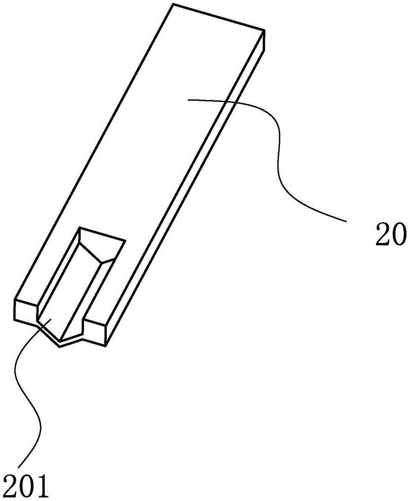
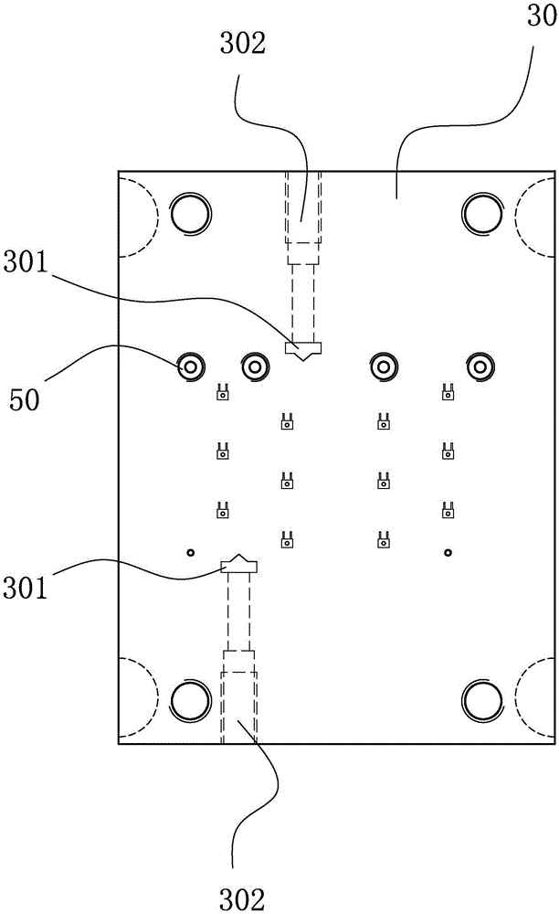
[0024] refer to Figure 1 to Figure 5 As shown, a preferred punching device provided in this embodiment includes: a punch 20, a stripping plate 30, a die 40, and the punching edge of the punch 20 is provided with a ventilation groove 201 with a length of L. , the stripper plate 30 and the die 40 are provided with a stripper plate through hole 301 and a die through hole 401 matching the shape of the punch, and the side of the stripper plate 30 to the position of the stripper plate through hole 301 is provided with a The air channel 302 corresponding to the ventilation groove 201 of the punch 20, the thickness of the discharge plate 30 is H, and the distance from the air channel 302 to the bottom surface of the discharge plate 30 is h, then the length L of the ventilation groove 201 satisfies h≤L≤H .
[0025] In this embodiment, the length L of the ventilation groove 201 satisfies h≤L≤H, so as to ensure that during the punching operation, the airflow of the air passage 302 blow...
Embodiment 2
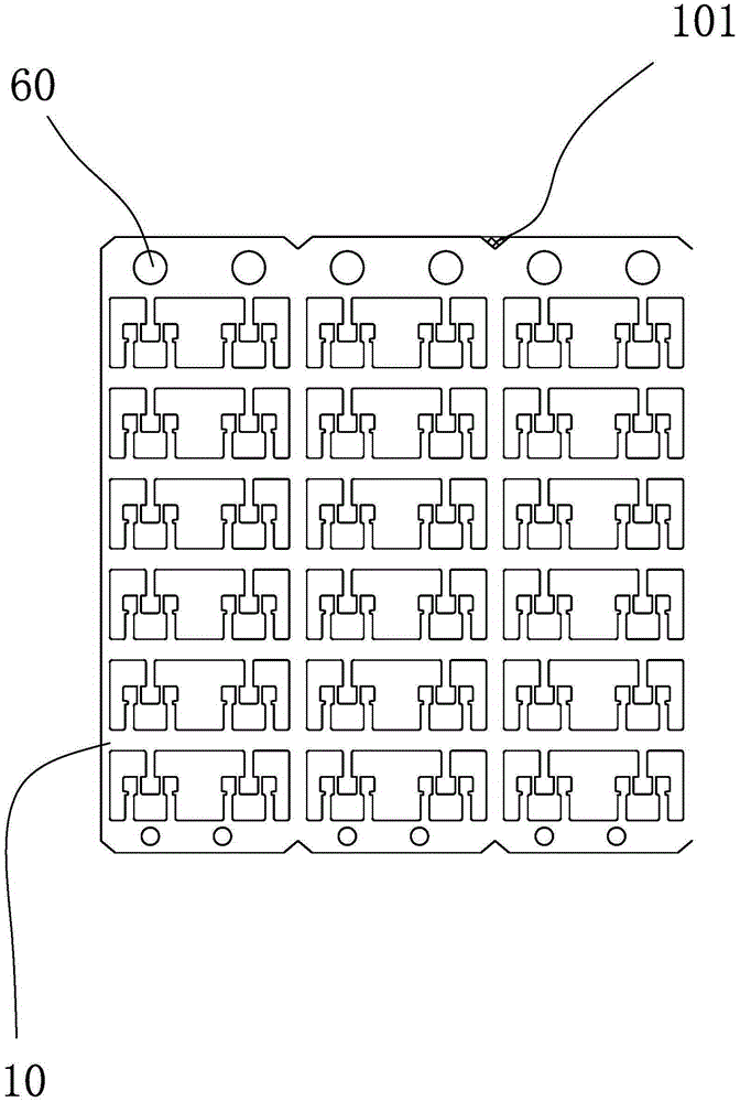
[0031] In this embodiment, the structure of the punch 20 and the die 40 is the same as that of the first embodiment, the only difference is that the inlet of the air channel 302 of the discharge plate 30 of this embodiment is located on the upper surface of the discharge plate 30, During the punching operation, the gas of the gas device enters through the inlet of the air passage 302 on the upper surface of the unloading plate 30, and the air flow of the air passage 302 flows to the ventilation groove 201 of the punch 20, and then is guided to the die by the ventilation groove 201 In the direction of the through hole 401 , after the cutting product 10 is punched, its waste 101 is blown out of the through hole 401 of the die under the drive of the airflow.
[0032] In this embodiment, the inlet of the air passage 302 of the unloading plate 30 is arranged on the upper surface of the unloading plate 30, which can shorten the time for setting the air passage 302 when the through ho...
PUM
 Abstract
Description
Claims
Application Information