Fully-hydraulic double-loop dynamic braking system
A dynamic braking and hydraulic circuit technology, applied in the direction of brakes, etc., can solve the problems of low utilization rate of ground adhesion coefficient, the braking effect needs to be improved, and the braking distance of the vehicle can be extended, so as to achieve a significant braking effect, improve the balance and stability. The effect of stability and labor intensity reduction
- Summary
- Abstract
- Description
- Claims
- Application Information
AI Technical Summary
Problems solved by technology
Method used
Image

Examples
Embodiment 1
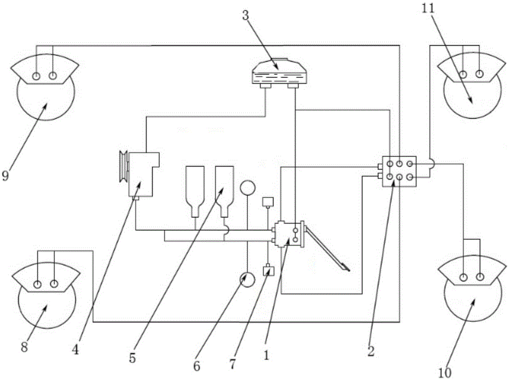
[0034] Such as figure 1 In the full hydraulic dual circuit braking system shown, the brake fluid from the fluid storage tank 2 is pressurized by the hydraulic pump 4 and then flows into the accumulator 5 for storage. When the driver depresses the brake pedal, the brake signal is transmitted For the brake valve 1, the oil inlet hole is connected to the oil outlet hole. Since the four brakes 8, 9, 10, and 11 of the car are connected to the oil outlet of the nonlinear load-sensing valve 2 in an X shape, the oil from the hydraulic pump 4 or the high-pressure oil of the accumulator 5 flows into the brake wheel cylinders of each wheel brake after passing through the pressure distribution of the nonlinear load-sensing valve 2, thereby braking the wheels. When the driver releases the brake pedal, the residual pressure oil in the brake line flows back to the liquid storage tank 3 through the oil return hole of the brake valve 1 . An accumulator 5 is provided therein, which can accumul...
Embodiment 2
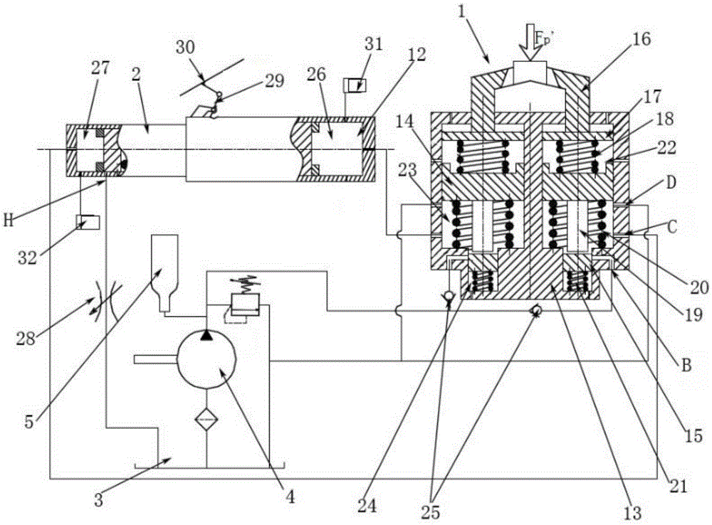
[0036] Such as figure 2 As shown, it is the structure of a single circuit and brake valve in the full hydraulic double circuit brake system. The hydraulic pump 4 and the accumulator 5 communicate with the oil inlet hole of the brake valve 1 through the check valve 25 and the pipeline. The oil outlet of the dynamic valve 1 communicates with the pressure regulating chambers 26 and 27 of the front and rear wheel cylinders of the nonlinear load-sensing valve 2 respectively, and the oil return hole of the brake valve 1 communicates with the low-pressure pipeline. The pressure relief hole H on the rear wheel cylinder pressure regulating cavity 27 of the nonlinear load-sensing valve 2 communicates with the low-pressure pipeline through a throttle valve 28 . The load-sensing lever 29 indirectly senses the load change of the vehicle by receiving the relative displacement change signal between the vehicle chassis 30 and the nonlinear load-sensing valve 2 . When the driver does not ste...
PUM
 Abstract
Description
Claims
Application Information
 - R&D
- Intellectual Property
- Life Sciences
- Materials
- Tech Scout
- Unparalleled Data Quality
- Higher Quality Content
- 60% Fewer Hallucinations
Browse by: Latest US Patents, China's latest patents, Technical Efficacy Thesaurus, Application Domain, Technology Topic, Popular Technical Reports.
© 2025 PatSnap. All rights reserved.Legal|Privacy policy|Modern Slavery Act Transparency Statement|Sitemap|About US| Contact US: help@patsnap.com