A roving frame for producing slub yarn

A technology of roving frames and slub yarns, which is applied to spinning machines, textiles, papermaking, and drafting equipment. It can solve the problems that the draft ratio cannot be changed in real time, the cost of spinning frames is high, and thick and thin knots cannot be formed. To achieve the effect of compact structure, low production cost and strong working reliability

Active Publication Date: 2017-11-24
QINGDAO TIANYI GROUP RED FLAG TEXTILE MACHINERY +1
View PDF8 Cites 0 Cited by
  • Summary
  • Abstract
  • Description
  • Claims
  • Application Information

AI Technical Summary

Problems solved by technology

[0004] At present, some slub yarns are spun on the basis of the original spinning frame, and a new spinning frame is formed by adding a set of adjustment systems and replacing corresponding components, such as the variable speed system of the front roller driven by a stepping motor to produce slub yarn , the slub yarn spun is generally five slubs with different pitches and lengths as a small cycle, and 25 slubs are formed sequentially as a large cycle, and the slub yarn device driven by a servo motor The length and pitch of the spinning can be set arbitrarily, and the thickness of the pitch can be changed arbitrarily at different ratios on the same yarn. Although this type of spinning frame can produce high-quality slub yarn, but its transformation of the original spinning frame The cost is also high, resulting in an increase in production costs
[0005] The spinning of some slub yarns is realized on the basis of the original roving frame. The drafting multiple of the ordinary wool spinning roving frame is changed through the process gear. The drafting multiple cannot be changed in real time, and the drafting multiple during spinning is fixed. , cannot form thick and thin knots, which will affect the quality of finished products

Method used


Image

  • A roving frame for producing slub yarn
  • A roving frame for producing slub yarn

Examples


Embodiment Construction

[0025] The present invention will be further described in detail below in conjunction with the accompanying drawings and specific embodiments, but the present invention is not limited to these embodiments.

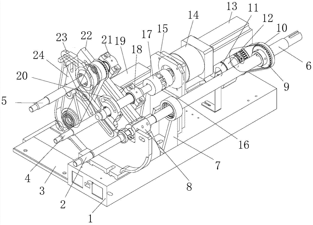
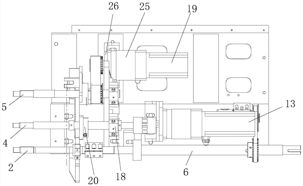
[0026] Such as figure 1 and figure 2 As shown, a roving frame for producing slub yarn includes a headstock, a drafting device, a headstock motor and a PLC controller are arranged on the headstock, and the drafting device includes a front seat board 1, a rear seat board 3 and a The first drafting roller 2, the second drafting roller 4 and the third drafting roller 5 above the rear seat plate, one end of the first drafting roller 2 is connected with a roller transmission shaft 6, and the roller transmission shaft 6 is driven by the head motor, The roller shaft of the first drafting roller 1 is connected to the above-mentioned roller transmission shaft 6 through the first coupling 8, the top end surface of the front seat plate 1 is provided with a bearing support 7, and the...


PUM


Abstract

The invention discloses a roving frame for producing slub yarn, which comprises a headstock, a drafting device, a headstock motor and a PLC controller are arranged on the headstock, and the drafting device includes a front seat board, a rear seat board, and a first drafting roller. , the second drafting roller and the third drafting roller, one end of the first drafting roller is connected with a roller transmission shaft, and the roller transmission shaft is driven by the head motor, and the top of the front seat board is provided with a device for supporting the first, second, third The first bracket and the second bracket of the drafting roller, the No. 1 servo motor for driving the second drafting roller is also arranged on the front seat, and the No. 2 servo motor for driving the third drafting roller is arranged on the rear seat. Both No. 1 and No. 2 servo motors are connected to the PLC controller, and the drafting device also includes a speed detector for detecting the speed of the above-mentioned roller drive shaft, and the speed detector is connected to the PLC controller. The invention can realize the real-time change of the draft ratio, is beneficial to form thick and fine details, and improves the product quality of the slub yarn.

Description

technical field [0001] The invention belongs to the technical field of slub yarn spinning, in particular to a roving frame for producing slub yarn. Background technique [0002] The slub yarn has the appearance of uneven thickness distribution, and it is one of the most types of fancy yarns. Slub yarn can be used for light summer fabrics and heavy winter fabrics, for clothing fabrics, and also for decorative fabrics, with outstanding patterns, unique style and strong three-dimensional effect. [0003] The thickness of the yarn is changed by changing the draft ratio of the spinning yarn during the spinning process of the slub yarn. [0004] At present, some slub yarns are spun on the basis of the original spinning frame, and a new spinning frame is formed by adding a set of adjustment systems and replacing corresponding components, such as stepping motors driving the variable speed system of the front roller to produce slub yarns , the slub yarn spun is generally five slubs...

Claims


Application Information

Patent Timeline
Patent Type & Authority Patents(China)
IPC IPC(8): D01H5/36D01H5/56
Inventor 吴海艳宋瑞华冯文成王秀红刘哲高玉刚
Owner QINGDAO TIANYI GROUP RED FLAG TEXTILE MACHINERY
Why Eureka
Try Eureka