Drop hammer-type compaction machine

A drop-weight, mechanical technology, used in roads, road repair, roads, etc., can solve problems such as limited operation, one-time compaction, and unsuitable joints between two bridge piers.

Inactive Publication Date: 2016-01-13
HEBEI UNIV OF ENG
View PDF6 Cites 3 Cited by
  • Summary
  • Abstract
  • Description
  • Claims
  • Application Information

AI Technical Summary

Problems solved by technology

[0002] In the process of highway construction and maintenance, in many cases, it is necessary to compact the floating soil on the road surface. The existing method is to use a roller truck for compaction, which has high compaction efficiency and a large compacted area, but for key stress-bearing parts, and The junction of two bridge piers is not suitable; Chinese application number 99119069.6 discloses a kind of drop hammer type compaction machine, which utilizes fixed parts to fix the soil stamping machine with the drop hammer on the carrier vehicle. The stamping machine includes a chassis support pad, a drop hammer Hammer and drop hammer control parts, the drop hammer is repeatedly lifted by the control part, and hits the chassis pad when it falls, thereby compacting the ground surface, the fixed part can make the drop hammer switch between the operating and non-operating states, and the driving part will move the drop hammer Moving along the end of the carrier vehicle, this drop hammer compaction machine is suitable for compacting the land near bridge piers, compacting the land in narrow trenches, and compacting the land in repairing small and scattered small road repairs; It can repair small roads, but its operation is limited, and it does not solve the key stress-bearing parts and the key compaction at the junction of the two bridge piers. Therefore, in the existing technology, it is still difficult to achieve one-time compaction for key parts equipment, and the general compaction process has only one mode

Method used


Image

  • Drop hammer-type compaction machine

Examples


Embodiment Construction

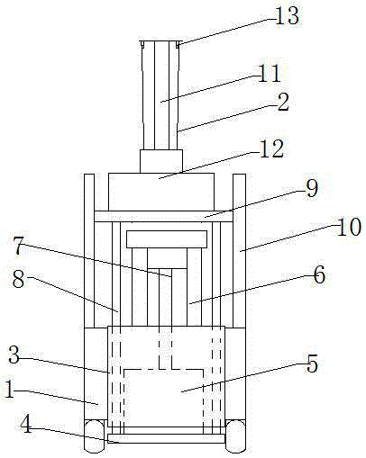
[0013] Such as figure 1 The shown drop hammer compaction machine includes a car body 1 and a drop hammer mechanism arranged at the front end of the car body; the drop hammer mechanism includes a fixed cavity 3; and a compaction plate arranged at the bottom of the fixed cavity 4; and the vibrating machine 5 arranged above the compaction plate; and the inner lifting mechanism support frame 6 provided on the top of the fixed cavity; and the inner lifting device 7 installed inside the top and the inner lifting mechanism support frame through the vibration machinery at the bottom And the external force application rod 8 that penetrates the fixed cavity and the bottom and the front sides of the compaction plate are installed in cooperation; and the force application platform 9 provided on the top of the external force application rod; and the external guide provided on the front side of the vehicle body The support 10; the force application platform 9 is movably fitted with the outer...


PUM


Abstract

The invention discloses a drop hammer-type compaction machine, which comprises a vehicle body, and a drop hammer mechanism arranged on the front end of the vehicle. The drop hammer mechanism comprises a fixed cavity, a compaction plate arranged on the bottom of the fixed cavity, a vibration machine arranged on the compaction plate, an inner lifting mechanism support frame arranged on the top of the fixed cavity, an inner lifting mechanism with the bottom penetrating through the vibration machine and with the top installed on the inner side of the inner lifting mechanism support frame, an external force rod penetrating through the fixed cavity and with the bottom in cooperation installation of on both sides of the front of the compaction plate, an external force platform arranged on the top of external force rod, and an external guide bracket arranged on the front of the vehicle. The vehicle has a guide rod vertically arranged on the rear middle part of the force platform; the guide rod is provided with a drop hammer; a traction wire is mounted at the top of the drop hammer; and the traction wire and a traction machine are in cooperative installation. The drop hammer-type compaction machine of the invention has three compaction modes to ensure strong force on the compaction part and high pressure withstand.

Description

Technical field [0001] The invention relates to a compaction mechanism, in particular to a drop hammer type compaction machine, belonging to the technical field of road maintenance equipment. Background technique [0002] In the process of highway construction and maintenance, in many cases, it is necessary to compact the pavement floating soil. The existing method is to use roller trucks for compaction. The compaction efficiency is high and the compaction area is large. However, for the key stress parts, and The two bridge pier joints are not suitable; Chinese application number 99119069.6 discloses a falling hammer type compaction machine, which uses a fixed part to fix a soil punch with a falling weight to the carrier. The punch includes a chassis support pad and a falling weight. The hammer and drop hammer control parts are repeatedly lifted by the control part and hit on the chassis support pad when falling, thereby compacting the ground surface. The fixed parts can make the...

Claims


Application Information

Patent Timeline
Patent Type & Authority Applications(China)
IPC IPC(8): E01C19/34
Inventor 赵强
Owner HEBEI UNIV OF ENG
Why Eureka
Try Eureka