
Hydraulic oil cylinder of thrust floating buffer industrial furnace

A technology for hydraulic cylinders and industrial furnaces, applied in the field of hydraulic cylinders, can solve problems such as mechanical structure damage

Active Publication Date: 2016-01-13
CHANGZHOU HYH HYDRAULIC EQUIP
View PDF4 Cites 1 Cited by
  • Summary
  • Abstract
  • Description
  • Claims
  • Application Information

AI Technical Summary

Problems solved by technology

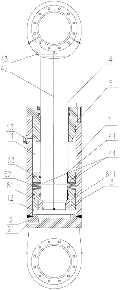
[0003] The technical problem to be solved by the present invention is: in order to solve the technical problem of damage to the oil cylinder seal, cylinder block, hydraulic system and the entire mechanical structure caused by excessive impact in the prior art, the present invention provides a thrust floating buffer industrial furnace hydraulic cylinder

Method used


Image

  • Hydraulic oil cylinder of thrust floating buffer industrial furnace

Examples


Embodiment Construction

[0012] The present invention is described in further detail now in conjunction with accompanying drawing. These drawings are all simplified schematic diagrams, which only illustrate the basic structure of the present invention in a schematic manner, so they only show the configurations related to the present invention.

[0013] Such as figure 1 Shown is the optimal embodiment of the present invention, a thrust floating buffer industrial furnace hydraulic cylinder, including a vertically installed cylinder body 1, the bottom end of the cylinder body 1 is a cylinder bottom 2, and a piston 3 is arranged in the cylinder body 1, The piston 3 is fixedly connected with the piston rod 4, the piston rod 4 is covered with a cylinder cover 5, the cylinder cover 5 is fixedly installed on the upper end of the cylinder body 1, the inner diameter of the piston rod 4 is smaller than the inner diameter of the cylinder body 1, and the piston 3 connects the cylinder body 1 The interior is divid...


PUM


Abstract

The invention relates to the technical field of hydraulic oil cylinders, in particular to a hydraulic oil cylinder of a thrust floating buffer industrial furnace. The hydraulic oil cylinder comprises a cylinder body vertically mounted, wherein the bottom end of the cylinder body is a cylinder bottom; a piston is arranged in the cylinder body, and is fixedly connected with a piston rod; the piston rod is coated with a cylinder cover; the cylinder cover is fixedly mounted at the upper end of the cylinder body; the inner diameter of the piston rod is smaller than the inner diameter of the cylinder body; the piston divides the cylinder body into a rod cavity and a rodless cavity; a floating buffer piston component for limiting the piston to upwards move is arranged in the rod cavity, and coats the piston rod; and an outer ring of the floating buffer piston component is tightly connected with the inner wall of the cylinder body. As the hydraulic oil cylinder of the thrust floating buffer industrial furnace is additionally provided with one set of floating buffer piston component in the rod cavity, when the descending of the oil cylinder is suddenly stopped, the pressure ascending speed of the rodless cavity is slowed down, and soft landing of a furnace body and molten steel is realized.

Description

technical field [0001] The invention relates to the technical field of hydraulic oil cylinders, in particular to a thrust floating buffer industrial furnace hydraulic oil cylinder. Background technique [0002] The hydraulic cylinder is the actuator in the hydraulic system. It is an energy conversion device that converts hydraulic energy into mechanical energy for reciprocating linear motion. It is generally composed of a cylinder body, a piston, a piston rod, and a cylinder head. The oil cylinders of industrial furnaces are installed vertically, and the rodless cavity is always stressed, and the load mass is relatively large, so the impact load will rise rapidly when the stop is stopped. Excessive impact will cause damage to the cylinder seal, cylinder block, hydraulic system and the entire mechanical structure . Contents of the invention [0003] The technical problem to be solved by the present invention is: in order to solve the technical problem of damage to the oil ...

Claims


Application Information

Patent Timeline
Patent Type & Authority Applications(China)
IPC IPC(8): F15B15/14F15B15/22
Inventor 陈新韩劲松吴榴花
Owner CHANGZHOU HYH HYDRAULIC EQUIP
Learn More