
A Conveyor with High Torque Output

A conveyor and high-torque technology, applied in the field of conveyors, can solve the problems of high manufacturing cost, achieve the effect of low cost, solve the problem of space layout, and simple structure

Active Publication Date: 2015-12-02
安吉县迎客松花木场
View PDF8 Cites 0 Cited by
  • Summary
  • Abstract
  • Description
  • Claims
  • Application Information

AI Technical Summary

Problems solved by technology

[0003] The purpose of the present invention is to provide a conveyor with high torque output, thereby solving the technical problem of high manufacturing cost of traditional belt conveyors

Method used


Image

  • A Conveyor with High Torque Output
  • A Conveyor with High Torque Output
  • A Conveyor with High Torque Output

Examples


Embodiment Construction

[0023] The present invention will be further described below with reference to the accompanying drawings.

[0024] The specific embodiment is only an explanation of the present invention, not a limitation of the present invention. Any modifications made by those skilled in the art after reading the description of the present invention will be protected by the patent law as long as they fall within the protection scope of the claims.

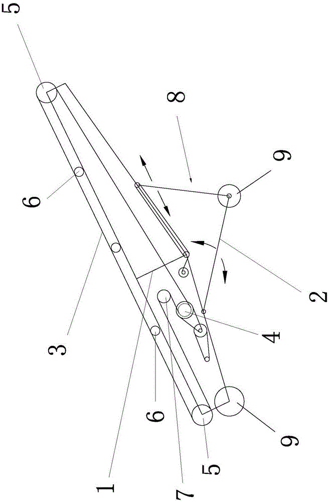
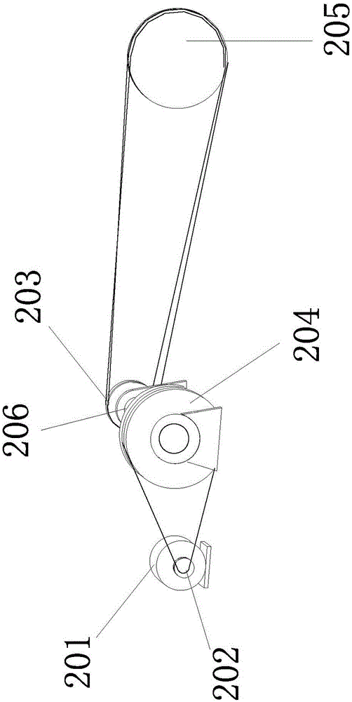
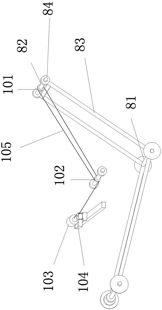
[0025] like Figure 1-3 As shown, a height-adjustable conveyor includes a conveyor frame 1 erected obliquely upward, a support frame 2 erected obliquely downward, a support frame 8, a conveyor belt 3, a power roller 4, a driven roller 5 and a support roller 6 , the support frame 8 includes a bottom crossbar 81, a support crossbar 82 and a vertical rod 83, the support crossbar 82 is rotatably connected with the vertical rod 83, the vertical rod 83 is rotatably connected with the bottom crossbar 81, and the support A supporting wheel 84 is provid...


PUM


Abstract

The invention relates to a conveyor with large torque output. The conveyor comprises a transmission rack which is erected upwards obliquely, a conveyer belt, a drive roller, a driven roller and a supporting roller, and is characterized in that the drive roller is connected to a second-level reduction gear which comprises a transmission motor, small belt pulleys A, B, big belt pulleys A, B and an intermediate shaft; the output shaft of the transmission motor is fixed with the small belt pulley A through a hinge pin; the small belt pulley A is connected with the big belt pulley A through a belt; the big belt pulley A is arranged on one end of the intermediate shaft through a hinge pin; the small belt pulley B is arranged on the other end of the intermediate shaft through a hinge pin, and is connected with the big belt pulley B through a belt; the big belt pulley B is directly fixed on a shaft of the drive roller through a hinge pin. The conveyor with large torque output has an ideal speed reducing effect, and the technical problem that the manufacturing cost of the traditional belt conveyor is high is solved.

Description

technical field [0001] The invention relates to a conveyor, in particular to a conveyor with large torque output. Background technique [0002] The conveyor uses the rotary motion or reciprocating motion of the working member, or the flow of the medium in the pipeline to transport the material forward. For example, the working member of the roller conveyor is a series of rollers, and the rollers rotate to transport the material; the working member of the screw conveyor is a screw, and the screw rotates in the trough to push the material along the trough; the work of the vibrating conveyor The component is a trough, and the trough reciprocates to transport the materials placed in it. A handling machine that continuously conveys materials on a certain line is called a continuous conveyor. Such conveyors mainly include belt conveyors, plate conveyors, trolley conveyors, escalators, moving walks, scraper conveyors, buried scraper conveyors, bucket conveyors, bucket elevators, ...

Claims


Application Information

Patent Timeline
Patent Type & Authority Patents(China)
IPC IPC(8): B65G23/24B65G23/44B65G21/10
Inventor 汪祥
Owner 安吉县迎客松花木场
Learn More