A buffer device for material pneumatic conveying system

A technology of pneumatic conveying and buffering device, which is applied in the field of buffering devices in the material pneumatic conveying system, which can solve the problems of poor buffering effect and damaged sample bottles, and achieve the effects of short buffering distance, extended service life and small space occupation

Active Publication Date: 2019-05-24
HUNAN SUNDY SCI & TECH DEV
View PDF6 Cites 0 Cited by
  • Summary
  • Abstract
  • Description
  • Claims
  • Application Information

AI Technical Summary

Problems solved by technology

Mechanical buffering can only achieve ideal buffering effect when the speed is lower than a certain value because the stiffness of the spring cannot be changed.
When the speed is fast and the weight is heavy, the cushioning effect is poor, and even the sample bottle may be damaged

Method used


Image

  • A buffer device for material pneumatic conveying system

Examples


Embodiment Construction

[0024] The present invention will be described in further detail below in conjunction with specific embodiments and accompanying drawings.

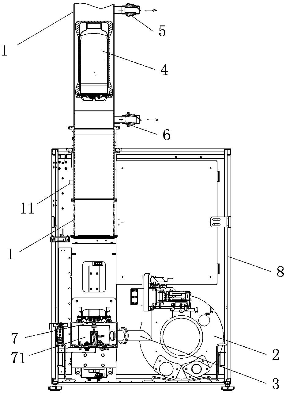
[0025] Such as figure 1 As shown, the present invention provides a buffer device for a material pneumatic conveying system, which is arranged at one end of a pneumatic conveying pipeline 1, and includes a buffer gas supply component 2 and an air supply pipeline 3, and the buffer gas supply component 2 communicates with the air supply pipeline 3 The pneumatic transmission pipeline 1 is connected, and when the conveying object 4 is transported through the pneumatic transmission pipeline 1, the buffer gas supply component 2 blows into the pneumatic transmission pipeline 1 through the air supply pipeline 3 to form an air pressure at one end of the pneumatic transmission pipeline 1 for conveying Object 4 forms a buffer (in the following description, for the convenience of corresponding description, the conveyed object 4 is exemplified as a sam...


PUM


Abstract

The invention discloses a buffering device used for a pneumatic material conveying system. The buffering device is arranged at one end of a pneumatic conveying pipeline, and comprises a buffering gas providing assembly and an air supply pipeline; the buffering gas providing assembly communicates with the pneumatic conveying pipeline through the air supply pipeline; and when conveyed objects are conveyed from the pneumatic conveying pipeline, the buffering gas providing assembly blows air into the pneumatic conveying pipeline through the air supply pipeline so that air pressure can be formed at one end of the pneumatic conveying pipeline and used for buffering the conveyed objects. The buffering device used for the pneumatic material conveying system has the advantages of being simple and compact in structure and good in buffering effect.

Description

technical field [0001] The invention mainly relates to the field of equipment for collecting and preparing material samples, and in particular to a buffer device for a material pneumatic conveying system. Background technique [0002] For the sampling, sample preparation, and testing of material (such as ore, coal) samples, each country has mandatory standards, and the sampling and processing of samples must be carried out in accordance with the standards. The principle of sample sampling, sample preparation, and testing work process is to gradually reduce the particle size and quality of the collected samples without destroying the representativeness of the sample, until it meets the particle size and quality of the sample in the laboratory test ( Weight) accuracy requirements, and then carry out relevant laboratory analysis on the samples that meet the requirements. For example, taking coal sampling as an example, it is actually a sampling and analysis process. The purpos...

Claims


Application Information

Patent Timeline
Patent Type & Authority Patents(China)
IPC IPC(8): B65G53/58
CPCB65G53/58
Inventor 朱先德肖兵球
Owner HUNAN SUNDY SCI & TECH DEV
Why Eureka
Try Eureka