
Crossing signal timing optimization method for reducing exhaust gas emission of motor vehicle

A technology of signal timing and optimization method, which is applied in the control of traffic signals, mechanical equipment, combustion engines, etc., and can solve problems such as differences and singleness of traffic flow operation laws that are not considered.

Active Publication Date: 2016-01-13
DALIAN UNIV OF TECH
View PDF8 Cites 26 Cited by
  • Summary
  • Abstract
  • Description
  • Claims
  • Application Information

AI Technical Summary

Problems solved by technology

[0005] (1) Carry out motor vehicle emission detection tests on different grades of urban roads using vehicle exhaust gas detection technology (PEMS), and discuss the correlation between traffic signal control and motor vehicle emissions through statistical analysis. The technical defect lies in the aggregated emissions The factor usually selects the average value of emission factors under different driving conditions;
[0006] (2) Introduce the atmospheric diffusion model or use traffic simulation software to establish an optimal model of intersection signal timing with the goal of reducing motor vehicle emissions. The difference in operating rules, and the influence of the left-turning short lane on the saturation flow rate of the entrance road is ignored

Method used


Image

  • Crossing signal timing optimization method for reducing exhaust gas emission of motor vehicle
  • Crossing signal timing optimization method for reducing exhaust gas emission of motor vehicle
  • Crossing signal timing optimization method for reducing exhaust gas emission of motor vehicle

Examples


Embodiment Construction

[0123] 1. Obtain traffic flow data and motor vehicle specific power partition data

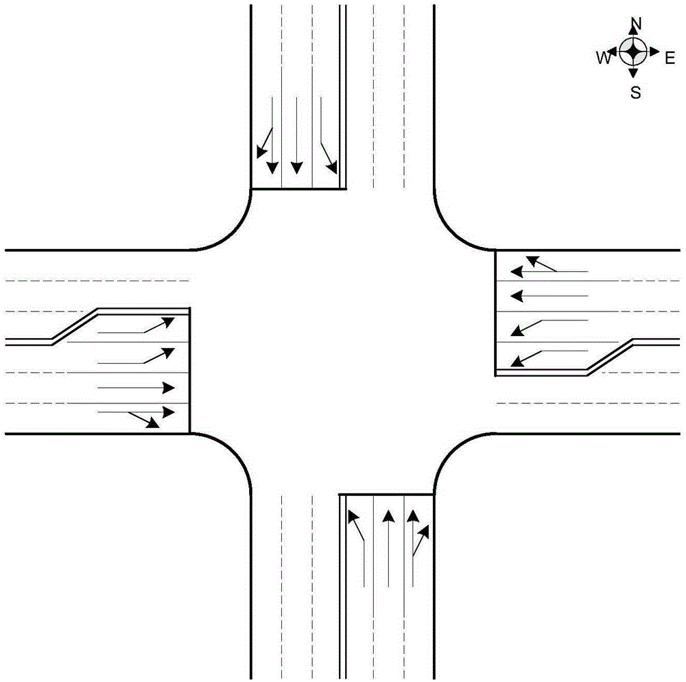
[0124] against figure 1 For the intersection shown, the traffic demand data in a typical time period is obtained according to the traffic survey, that is, the hourly traffic flow and the peak 15-min flow rate of each entrance road and each turning traffic flow. Here, it is assumed that the traffic flow is composed of 100% cars, and three demand levels are considered, and the traffic demand data shown in Table 1 is obtained by random generation. In addition, it is assumed that the gradient of each road is 0.

[0125] Table 1 Hourly traffic flow and peak 15-min flow rate of each turning traffic flow at each entrance under different demand levels

[0126]

[0127] Calibrate the saturated flow rate of each entrance lane based on traffic survey or practical experience. Here, it is assumed that the saturated flow rate of the left-turn lane and the right-hand lane are both 1810pcu / h, and the sat...


PUM


Abstract

The invention discloses a crossing signal timing optimization method for reducing exhaust gas emission of a motor vehicle, and is applied to a single-point signal control crossing with (without) a left-turn short lane. An emission factor calibration method during red light and green light periods is brought forward based on motor vehicle specific power, and a signal timing optimization model of a minimum motor vehicle emission amount is constructed according to a traffic flow theory and operational research. Three common pollutants including CO, HC and NOx are taken into consideration, a traffic simulation experiment is designed by use of VISSIM software, a parameter calibration and model solution algorithm is compiled by use of MATLAB software, two emission factors of each pollutant of each lane are calibrated according to vehicle driving condition data, and a new signal timing optimization model is verified by use of traffic flow data. Results show that the emission factors during the green light period are higher than the emission factors during the red-light period, and the new method can reduce both vehicle delay and traffic emission. The method provided by the invention facilitates simultaneous reduction of the vehicle delay at a crossing and the traffic emission through optimization of a conventional signal timing scheme, thereby being widely applied to design of a single-point crossing signal timing scheme.

Description

technical field [0001] The invention belongs to the field of intelligent traffic control, and relates to a signal timing optimization method suitable for single-point control intersections with (without) left-turn short lanes and reducing exhaust emissions of motor vehicles. Background technique [0002] Today, environmentally friendly and sustainable development is a focus of widespread concern around the world. Motor vehicle exhaust emissions, as one of the main sources of environmental pollution, need to be effectively controlled through advanced energy-saving and emission-reduction technologies. [0003] Signal-controlled intersection is an important part of urban road network, and whether it is smooth or not plays a key role in the operation efficiency of the entire road network. At the same time, the reduction of motor vehicle exhaust emissions at intersections will also reduce the motor vehicle exhaust emissions of the entire road network, thereby improving the enviro...

Claims


Application Information

Patent Timeline
IPC IPC(8): G08G1/07
CPCY02T10/40
Inventor 姚荣涵王筱雨徐洪峰赵胜川
Owner DALIAN UNIV OF TECH
Learn More