Monitoring control device for working condition of generator

A working status, monitoring and control technology, applied in the direction of controlling generators, control systems, electrical components, etc., can solve problems such as potential safety hazards, failure to issue control commands to generators, and inability to know the working status of generators in real time, to achieve The effect of improving the safety and convenience of use

Inactive Publication Date: 2016-01-13
CHONGQING KAIBI TECH
6 Cites 0 Cited by

AI-Extracted Technical Summary

Problems solved by technology

In terms of status monitoring, it must be completed next to the generator. When the staff is far away from the generator, they cannot know the working status of the generator in real time, a...

Method used

During work, collect and transmit the operating state parameter of generator by sensor group, single-chip microcomputer processes state parameter, and the parameter after processing is sent to far-end client by transmission group, and operator checks power generation by far-end client The working state of the generator is issued by the remote client to control th...

Abstract

The invention discloses a monitoring control device for a working condition of a generator. The monitoring control device comprises a single chip microcomputer, a sensor group, a transmission group, a controller group and a power pack, wherein the sensor group is electrically connected with the single chip microcomputer; the single chip microcomputer is electrically connected with the transmission group, a control unit and a power supply unit; the sensor group comprises an engine oil temperature detection control unit, a gasoline detection control unit and a generator temperature detection unit, which are electrically connected with the single chip microcomputer respectively; the control group comprises a generator electronic lighting drive control unit and a generator electronic lighting detection unit; and the generator electronic lighting drive control unit drives the control unit to receive a control instruction sent by the single chip microcomputer, and controls a generator electronic lighting coil to work through the generator electronic lighting detection unit. The monitoring control device can monitor the working state of the generator, and can achieve a remote or automatic control on the generator according to the monitored data.

Application Domain

Electric generator control

Technology Topic

Automatic controlElectricity +8

Image

  • Monitoring control device for working condition of generator

Examples

  • Experimental program(1)

Example Embodiment

[0016] The present invention will be further described below with reference to the drawings and embodiments.
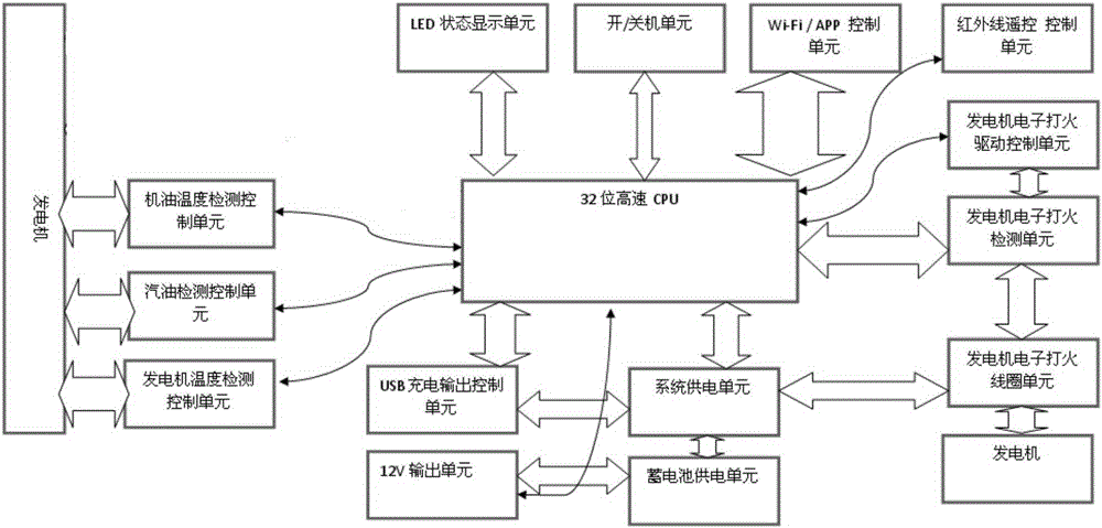
[0017] The monitoring and control device for the working state of the generator includes a single-chip microcomputer, a sensor group, a transmission group, a controller group, and a power supply group. The sensor group is electrically connected to the single-chip microcomputer, and the single-chip microcomputer is electrically connected to the transmission group, the control unit and the power supply unit. The group includes an oil temperature detection control unit, a gasoline detection control unit, and a generator temperature detection unit that are electrically connected to the single-chip microcomputer. The control group includes a generator electronic ignition drive control unit and a generator electronic ignition detection unit for generating electricity. The mechanical electronic ignition drive control unit receives the control instructions sent by the single-chip microcomputer, and controls the generator electronic ignition coil to work through the generator electronic ignition detection unit.
[0018] The oil temperature detection control unit, gasoline detection unit and generator temperature detection unit all adopt A/D sampling. The generator electronic ignition drive unit drives the control unit to generate a large current through the PWM mode of the CPU, and the high voltage drives the generator ignition motor. The generator electronic ignition detection unit detects the starting state of the generator, and the CPU determines whether the ignition drive unit that controls the generator stops working.
[0019] When working, the working state parameters of the generator are collected and transmitted through the sensor group. The single-chip microcomputer processes the state parameters and sends the processed parameters to the remote client through the transmission group. The operator can view the working state of the generator through the remote client. , Through the remote client to send control instructions to control the generator to work, the monitored generator working status parameters include the oil temperature and the generator temperature. The invention can monitor the working state of the generator, realize remote or automatic control of the engine according to the monitored data, and improve the safety and convenience of the generator.
[0020] The transmission group includes a Wi-Fi control unit and an infrared remote control control unit, and the Wi-Fi control unit and the infrared remote control control unit are respectively electrically connected with the single-chip microcomputer. The remote client can interact with the present invention through infrared and Wi-Fi data. The Wi-Fi control unit uses a mobile phone or mobile device to remotely view the generator status and control the generator through the communication protocol; the infrared remote control unit remotely controls the switch of the generator through the infrared remote control.
[0021] The power supply group includes a system power supply unit and a battery power supply unit, and the battery power supply unit is electrically connected to the single-chip microcomputer through the system power supply unit. When working, indoor power supply or storage battery can provide working power for the present invention.
[0022] The device also includes a USB charging output control unit and a 12V output unit. The USB charging output control unit interacts with the single-chip microcomputer and is electrically connected to the system power supply unit. The 12V output unit provides power for the battery power supply unit. The USB charging output control unit uses digital detection of the charging current to limit the charging current. Fully automatically stops.
[0023] The single-chip microcomputer is a 32-bit high-speed CPU.
[0024] Finally, it should be noted that the above embodiments are only used to illustrate the technical solutions of the present invention and not to limit them. Although the present invention has been described in detail with reference to the preferred embodiments, those of ordinary skill in the art should understand that the technical solutions of the present invention can be implemented Modifications or equivalent replacements without departing from the purpose and scope of the technical solution should be covered by the scope of the claims of the present invention.

PUM

no PUM

Description & Claims & Application Information

We can also present the details of the Description, Claims and Application information to help users get a comprehensive understanding of the technical details of the patent, such as background art, summary of invention, brief description of drawings, description of embodiments, and other original content. On the other hand, users can also determine the specific scope of protection of the technology through the list of claims; as well as understand the changes in the life cycle of the technology with the presentation of the patent timeline. Login to view more.

Similar technology patents

Self locking mechanism and unmanned aerial vehicle

PendingCN106965920AThe structure takes up little spaceImproved safety and convenience of use
Owner:安元(徐州)大数据科技有限公司

Code zero-clearing mechanism of coded lock

PendingCN108193949AImproved safety and convenience of use
Owner:苏州琨山智能科技有限公司

Classification and recommendation of technical efficacy words

  • Improved safety and convenience of use

Self locking mechanism and unmanned aerial vehicle

PendingCN106965920AThe structure takes up little spaceImproved safety and convenience of use
Owner:安元(徐州)大数据科技有限公司

Code zero-clearing mechanism of coded lock

PendingCN108193949AImproved safety and convenience of use
Owner:苏州琨山智能科技有限公司
Why Eureka
Try Eureka