
Multiband antenna system

A multi-band antenna, multi-band technology, applied to antennas, devices that make antennas work in different bands at the same time, electrical components, etc., can solve problems such as increasing size and increasing cost

Inactive Publication Date: 2016-01-13
古特尔株式会社
View PDF6 Cites 2 Cited by
  • Summary
  • Abstract
  • Description
  • Claims
  • Application Information

AI Technical Summary

Problems solved by technology

That is, in the case of five terminals, the length ratio to the center of the rotating body needs to be 2 to 1, and in the case of four terminals, the length ratio needs to be 3 to 1, so the size will instead be larger
This becomes the reason why phase converters used in the same frequency band also have different sizes, and causes an increase in cost

Method used


Image

  • Multiband antenna system
  • Multiband antenna system
  • Multiband antenna system

Examples


Embodiment Construction

[0086] It should be understood that in the following description, only the parts necessary for understanding the embodiments of the present invention will be described, and descriptions of the remaining parts will be omitted to avoid obscuring the gist of the present invention.

[0087] The terms or expressions used in the specification and claims described below should not be construed as being limited to common meanings or dictionary meanings; The definition is to explain the principles of one's own invention in the best way, interpret the meaning and concept as the technical thought of the present invention. Therefore, the embodiments described in this specification and the structures shown in the drawings are only preferred embodiments of the present invention, and they do not represent all technical ideas of the present invention, so it should be understood that there may be Various equivalents and modifications can be substituted for them.

[0088] Hereinafter, embodime...


PUM


Abstract

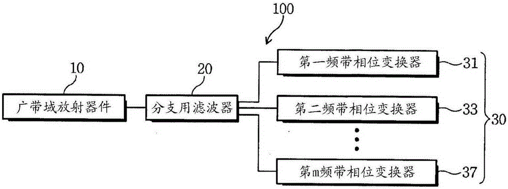
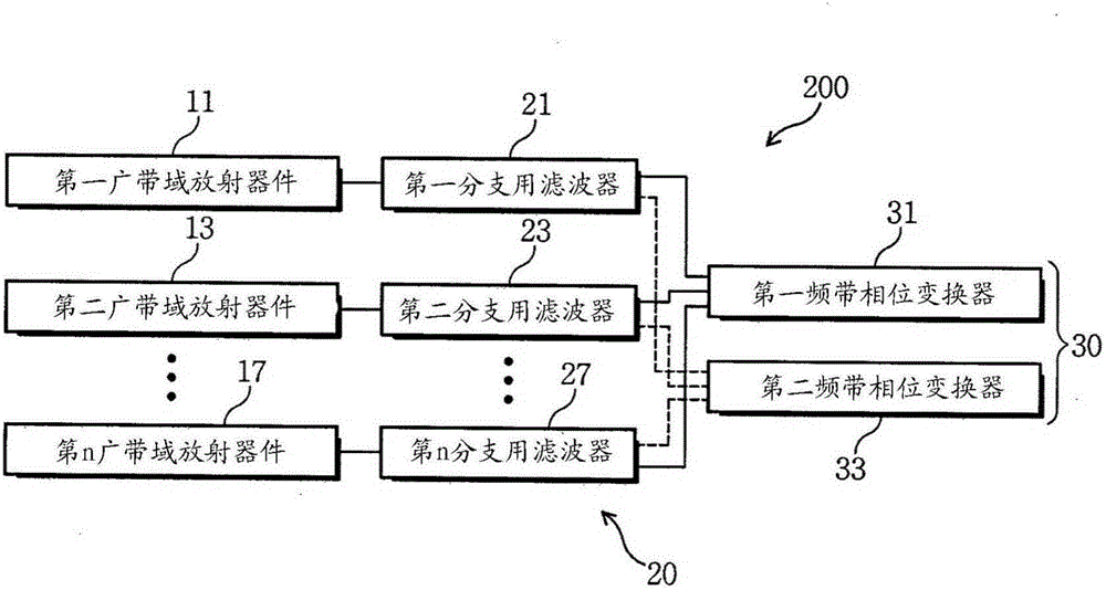
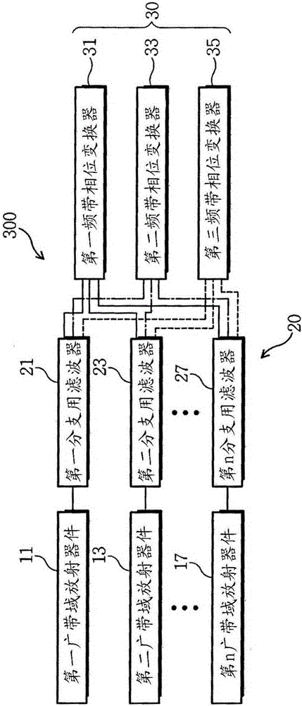
The present invention relates to a multiband antenna system and, more particularly, to a multiband antenna system which performs beam tilt while servicing a multiband with a broadband radiating element supporting a multiband. The multiband antenna system according to the present invention comprises: at least one broadband radiating element; a branching filter; and a plurality of phase shifters. The at least one broadband radiating element supports a multiband. The branching filter is connected to each of the at least one broadband radiating element and branches signals per band included in the multiband. The plurality of phase shifters is provided to correspond to the number of the multibands and perform beam tilt for the signals branched per band in accordance with each band. Here, the band means not a band for dividing receipt and transmission in a particular band, but a service band per service provider.

Description

technical field [0001] The present invention relates to an antenna system, and more particularly to a multi-band antenna system capable of tilting beams while providing multi-band services through a wide-band radiation device supporting multi-bands. Background technique [0002] With the diversification of communication services, a service provider will be allocated multiple frequency bands (bands), so when building base stations and relay stations, it is necessary to set antennas according to the frequency bands of various services. [0003] As a result, multiple service frequency bands of multiple service providers will be built on the towers of the base station and relay station. However, since the tower has a limited installation space, the number of antennas that can be installed is limited. In addition, when too many antennas are installed on the tower, it will affect the beauty of the city. [0004] To reduce this problem, service providers use multi-band antennas th...

Claims


Application Information

Patent Timeline
Patent Type & Authority Applications(China)
IPC IPC(8): H01Q3/26H01Q5/10
CPCH01Q5/50H01Q3/30H01Q5/00
Inventor 朴镇泳
Owner 古特尔株式会社
Learn More