
Mechanical and electrical integration spindle box and auxiliary structure of instrument lathe

A technology for instrument lathes and spindle boxes, applied in mechanical equipment, manufacturing tools, metal processing machinery parts, etc., can solve the problems of small axial installation space, large rod noise and energy consumption, large mechanical vibration, etc. Improved, improved safety, high precision effects

Inactive Publication Date: 2016-01-20
陈江源 +1
View PDF2 Cites 0 Cited by
  • Summary
  • Abstract
  • Description
  • Claims
  • Application Information

AI Technical Summary

Problems solved by technology

Among them, the structure of the belt transmission is simple, the cost is low, and the axial installation space is small, but the mechanical vibration of high-speed rotation is large, and the motor needs more installation space to connect the belt pulley; the gear transmission structure is compact and complicated, but the noise and energy consumption of the teeth are large.

Method used


Image

  • Mechanical and electrical integration spindle box and auxiliary structure of instrument lathe
  • Mechanical and electrical integration spindle box and auxiliary structure of instrument lathe
  • Mechanical and electrical integration spindle box and auxiliary structure of instrument lathe

Examples


Embodiment Construction

[0030] The present invention will be further described below in conjunction with the specific implementation manner of accompanying drawing:

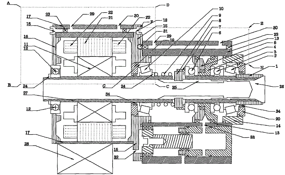
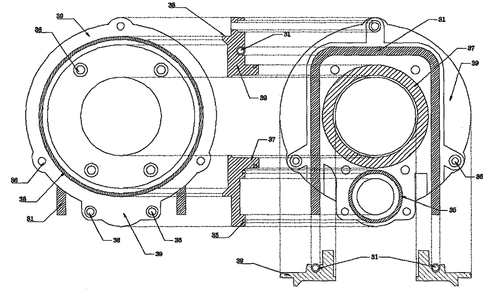
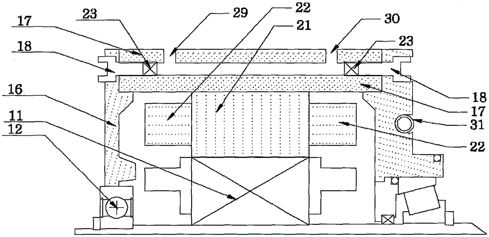
[0031] figure 1Shown is the half-section diagram of the overall embodiment of the present invention, as shown in the figure: the clamping mechanism of the instrument lathe is built in the main cylinder of the main shaft box (13); the motor rotor (11) is installed in the hollow main shaft (27); the motor stator (21) Installed on the motor casing (17); the motor casing (17) is coaxially fixed to the main cylinder of the main shaft box (13) through the flange (15); the front end of the main shaft box (13) is provided with a front cover (14) and a seal Cover; the rear end of the motor casing (17) is provided with a rear end cover (16); the front end cover (14) is installed with a front support bearing (2); the flange (15) is installed with a rear support bearing (10); the rear end cover (16) Auxiliary bearings (12) are installed; wear-resi...


PUM


Abstract

The technical scheme that a spindle box (13) is used for oil bath lubrication, a flange plate (15) is used for transition, and a motor shell (17) is arranged on the rear portion, the technical scheme that a hollow spindle (27) is mounted in a three-supporting-point manner through a front supporting bearing (2), a rear supporting bearing (10) and an auxiliary bearing (12), a wear-proof shaft sleeve (1), the front supporting bearing (2) and a first thrust bearing (3) are arranged at the front end of the hollow spindle (27), the middle segment of the spindle is in movable fit with a second thrust bearing (6) and is sequentially provided with a first piston (4), a second piston (5), the second thrust bearing (6), a sliding block sleeve (7), a thrust sliding block (8) and a spring (9), and the rear supporting bearing (10), a motor rotor (11) and the auxiliary bearing (12) are arranged at the rear end of the spindle, and the technical scheme that water cooling is carried out in the spindle box (13), the flange plate (15) and the motor shell (17) independently are mainly adopted. The beneficial effects that the space utilization rate and the number of use turns of an instrument lathe are increased, mechanical noise is lowered, safety is improved, and energy saving and emission reduction are achieved are achieved.

Description

technical field [0001] The invention belongs to the mechanical field and relates to an electromechanical integration structure of a spindle box of an instrument lathe. technical background [0002] At present, the clamping mechanism of the traditional instrument lathe is that the chuck at the front end is connected to the hollow tie rod, and the pull rod works in a way that the pull rod passes through the hollow main shaft and is connected with the tensioning mechanism at the rear end. Therefore, the transmission mode is basically belt drive or gear drive. Among them, the belt transmission has a simple structure, low cost, and small axial installation space, but the mechanical vibration of high-speed rotation is large, and more installation space is required for the motor to connect to the belt pulley; the gear transmission structure is compact and complicated, but the noise and energy consumption of the teeth are large. Contents of the invention [0003] With the improve...

Claims


Application Information

Patent Timeline
Patent Type & Authority Applications(China)
IPC IPC(8): B23B19/00F16H57/021F16H57/029F16H57/04
CPCB23Q1/70F16H57/021F16H57/029F16H57/04F16H57/0412
Inventor 陈江源
Owner 陈江源
Learn More