a slotting machine

A grooving machine and grooving technology, applied in the direction of shearing devices, shearing machine accessories, shearing machine equipment, etc., can solve the problems of inconvenient adjustment and inconvenient operation, and achieve good grooving effect, convenient operation, Easy to adjust the effect

Active Publication Date: 2017-12-15
ZHEJIANG SANLIN METALS PROD
View PDF5 Cites 0 Cited by
  • Summary
  • Abstract
  • Description
  • Claims
  • Application Information

AI Technical Summary

Problems solved by technology

[0003] The purpose of the present invention is to provide a slotting machine to solve the problems of inconvenient adjustment and inconvenient operation of traditional cloth slotting equipment

Method used


Image

  • a slotting machine
  • a slotting machine
  • a slotting machine

Examples


Embodiment Construction

[0023] In order to make the technical means, creative features, goals and effects achieved by the present invention easy to understand, the present invention will be further elaborated below in conjunction with illustrations and specific embodiments.

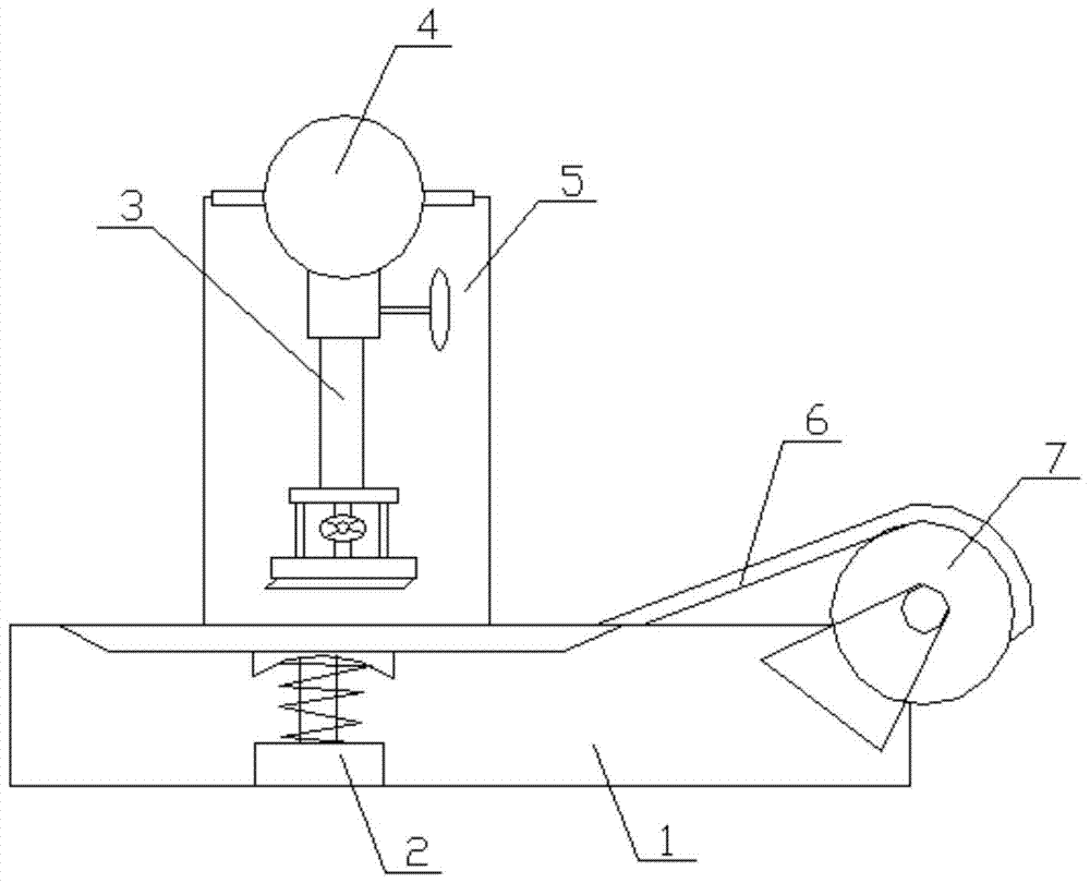
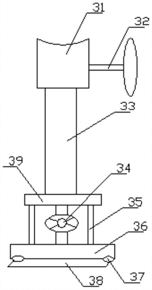
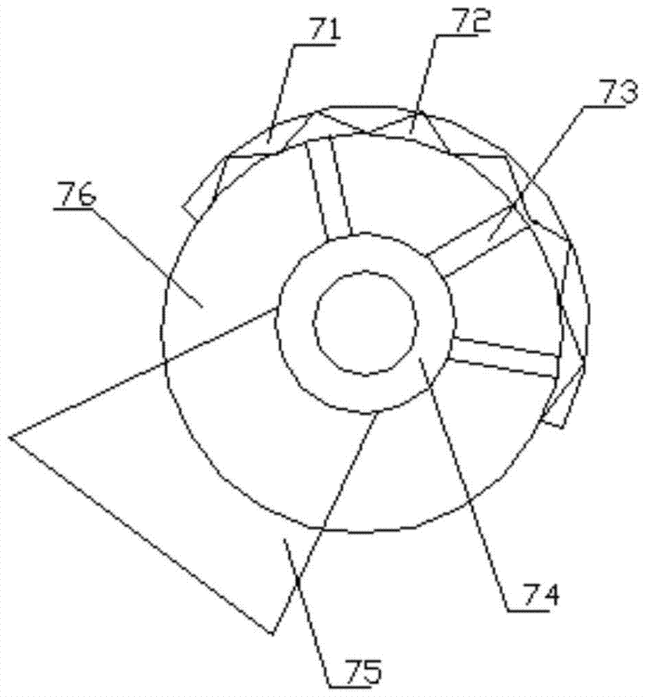
[0024] combine Figure 1 to Figure 4 The grooving machine of the present invention will be described in detail.

[0025] The slotting machine of the present invention includes a base 1, and also includes a frame 5 arranged on the upper end of the base 1, a first driving part 4 arranged on the top of the frame 5, and a first driving part 4 screwed on the first The slotting part 3 at the bottom of a driving part 4, the support part 2 arranged on the base 1 and at the lower side of the slotting part 3, the second driving part arranged at the upper part of the base 1 7 and the transmission part 6 coated on the outside of the second drive part 7; the grooved part 3 includes a main transmission rod 33, a transmission seat 31 arranged...


PUM


Abstract

The present invention relates to the technical field of mechanical equipment, in particular to a slotting machine; the slotting machine of the present invention includes a base, a frame, a first driving part, a slotting part, a supporting part, a second driving part and a transmission Parts; the grooving part includes a main transmission rod, a transmission seat, an adjustment knob, a first mounting plate, a lifting adjustment member, a second mounting plate, an auxiliary lifting rod, a main cutting knife and a fine-tuning device arranged on the main cutting knife parts; the grooving machine of the present invention is easy to operate, convenient to adjust, and has high grooving efficiency.

Description

technical field [0001] The invention relates to the technical field of mechanical equipment, in particular to a slotting machine. Background technique [0002] Grooving is required during the processing of sheet metal. However, the traditional grooving equipment is inconvenient to adjust, inconvenient to operate, low in grooving efficiency, and poor in grooving quality. Therefore, it is necessary to provide a grooving device with convenient operation, convenient adjustment, high grooving efficiency, and grooving quality. Contents of the invention [0003] The purpose of the present invention is to provide a slotting machine to solve the problems of inconvenient adjustment and inconvenient operation of traditional cloth slotting equipment. [0004] The technical scheme that the present invention adopts for solving its technical problem is: [0005] A slotting machine, comprising a base, further comprising a frame set on the upper end of the base, a first drive part set o...

Claims


Application Information

Patent Timeline
Patent Type & Authority Patents(China)
IPC IPC(8): B23D31/00B23D33/02
Inventor 李强
Owner ZHEJIANG SANLIN METALS PROD
Why Eureka
Try Eureka