Robot and robotic system

A robot and feeder technology, applied in the direction of robots, manipulators, auxiliary devices, etc., can solve the problems of large space and small space, and achieve the effect of restraining space and compact appearance

Inactive Publication Date: 2016-01-20
YASKAWA DENKI KK
View PDF7 Cites 9 Cited by
  • Summary
  • Abstract
  • Description
  • Claims
  • Application Information

AI Technical Summary

Problems solved by technology

[0006] However, in the prior art described above, there is room for further improvement in terms of reliably preventing interference with surrounding objects or suppressing the space installed around the robot.
[0007] For example, in the above-mentioned robot, there is the following problem: the above-mentioned feeder main body is arranged on the outside of the arm, and the wire passes through the outside of the arm, so it is easy to interfere with surrounding objects. Set up a large space around

Method used


Image

  • Robot and robotic system
  • Robot and robotic system
  • Robot and robotic system

Examples


Embodiment Construction

[0024] Hereinafter, embodiments of the robot and the robot system disclosed in the present application will be described in detail with reference to the drawings. In addition, this invention is not limited to embodiment shown below.

[0025] In the following, a robot used for arc welding will be described as an example. In addition, the welding torch is described as "welding torch".

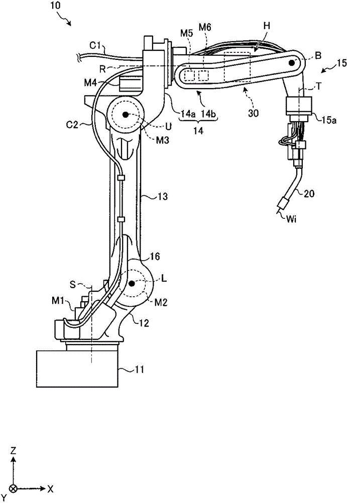
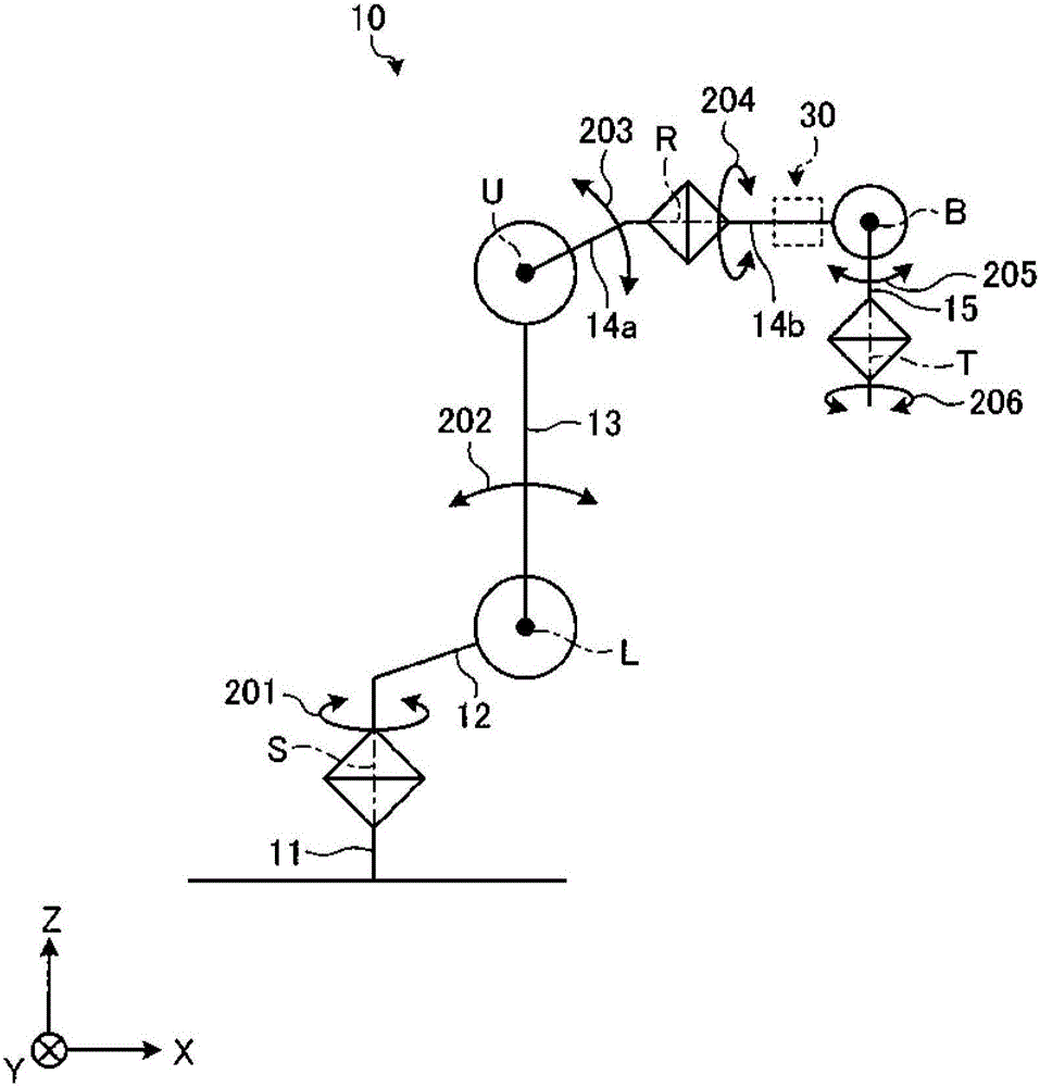
[0026] First, the outline of the robot 10 of the embodiment will be described. Figure 1A It is a schematic side view of the robot 10 of the embodiment. In addition, in the following, for convenience of description, it is assumed that the rotational position and posture of the robot 10 are basically at Figure 1A The state shown is the description of the positional relationship of each part in the robot 10 . In addition, sometimes the Figure 1A The state shown is referred to as the "basic posture" of the robot 10 .

[0027] In addition, the installation surface side of the base portion 11 on ...


PUM


Abstract

The invention provides a robot and a robotic system with a compact profile, more reliably preventing from interference of surrounding articles, reducing the space around the robot. The robot includes: a mounting portion on which a welding torch is mountable; an arm portion having a tip portion, the arm portion swingably supporting the mounting portion (15) at the tip portion; an arm supporting portion having a tip portion, the arm supporting portion supporting the arm portion rotatably around a rotation axis at the tip portion, the rotation axis being perpendicular to a swinging axis of the mounting portion ; a space, forming between the tip portion of the arm portion and a base end along the axis line of the rotation axis; and a feeding device arranged in the space to intersect with an axis line of the rotation axis, the feeding device being configured to feed a wire to the welding torch mounted on the mounting portion.

Description

technical field [0001] The disclosed embodiments relate to robots and robotic systems. Background technique [0002] Conventionally, robots used for arc welding are known. This robot is configured to have a multi-axis arm, and a welding torch as an end effector (hereinafter referred to as "welding torch") is attached to a movable terminal portion of the multi-axis arm. [0003] In addition, the wire for welding is fed to the welding torch. This feeding is carried out by a wire feeding device (hereinafter referred to as "feeder"), and the wire feeding device uses a plurality of rotating rollers to sandwich and feed the wire (for example, refer to Patent Document 1). [0004] The feeder main body including the above-mentioned plurality of rotating rollers is attached, for example, to the outside of an arm supporting the above-mentioned terminal movable portion. That is, the wire is fed through the outside of the arm. [0005] Patent Document 1: Japanese Patent Laid-Open N...

Claims


Application Information

Patent Timeline
Patent Type & Authority Applications(China)
IPC IPC(8): B23K9/12B23K9/133B23K37/02
CPCB23K9/12B23K9/133B23K37/0252B25J19/0025B23K9/287B23K9/1336Y10S901/42B25J15/0019B25J19/0029
Inventor 伊泽多闻斋藤洋一番濑敦
Owner YASKAWA DENKI KK
Why Eureka
Try Eureka