
Calibration method and device for laser marking

A technology of laser marking and calibration method, applied in the field of laser marking, can solve the problems of difficulty in measuring the number of points, time-consuming, troublesome operation, etc.

Active Publication Date: 2017-04-12
MAXPHOTONICS CORP
View PDF4 Cites 0 Cited by
  • Summary
  • Abstract
  • Description
  • Claims
  • Application Information

AI Technical Summary

Problems solved by technology

The disadvantage of this method is that when a high-density and high-precision deviation table needs to be measured, the operation is cumbersome and time-consuming, and it is difficult to measure a large number of points

Method used


Image

  • Calibration method and device for laser marking
  • Calibration method and device for laser marking
  • Calibration method and device for laser marking

Examples


Embodiment Construction

[0049] In order to make the above objects, features and advantages of the present application more obvious and comprehensible, the present application will be further described in detail below in conjunction with the accompanying drawings and specific implementation methods.

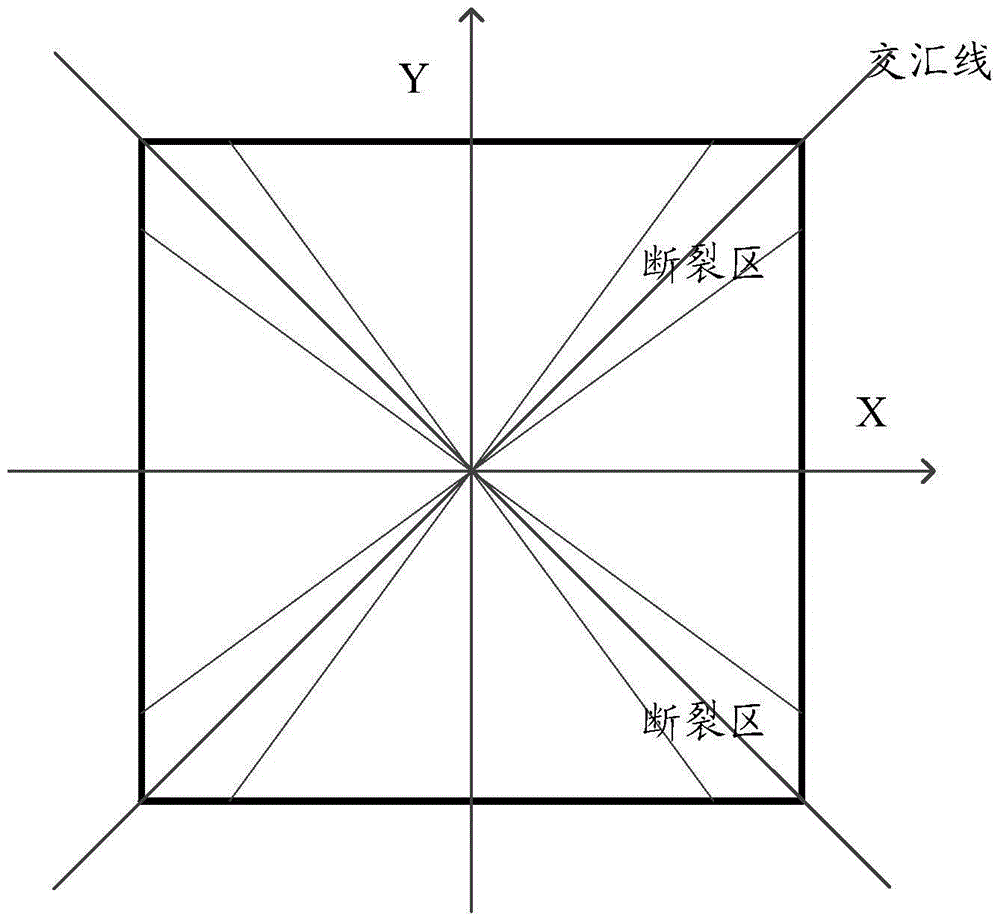
[0050] like image 3 As shown, when printing a square using the formula method, first intercept N points on the uncorrected marking image, measure the deviation between the actual coordinates of these N points and the ideal coordinates, and use the fitting method, Fit these N points into a curve equation, which is the deviation equation of each marking point coordinate after distortion. In this way, the four curve formulas of the four sides will be obtained. After the formula is obtained, the deviation value of each point on the marking plane can be known. When actually marking, the deviation of each coordinate point is first calculated, and the The deviation of the coordinates is added to the actual co...


PUM


Abstract

An embodiment of the present application provides a calibration method for laser marking, including: acquiring an image to be marked; determining a fractured area and a non-fractured area of ​​the image to be marked in a coordinate system preset by a laser marking machine; Use the preset correction formula to correct the non-fracture area of ​​the image to be marked; use the preset standard correction value and the preset weighting coefficient corresponding to the coordinate position to correct the fracture area of ​​the image to be marked; use the corrected image to be marked Marking. In the present application, the correction of the distortion of the fracture zone is realized by weighting and correcting the marking points in the fracture zone according to subdivided coordinate positions. And there is no need to measure the deviation value of the high-density and high-precision marking area.

Description

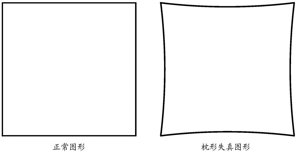
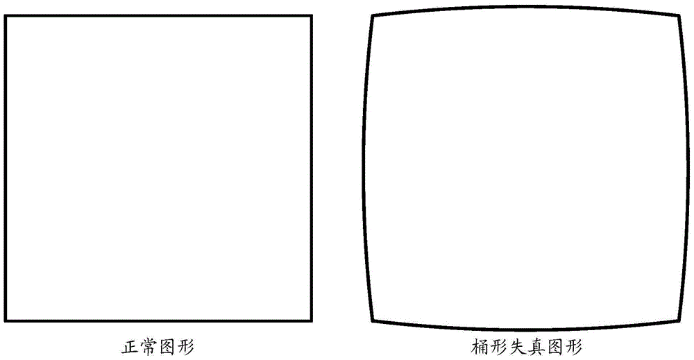
technical field [0001] The present application relates to the technical field of laser marking, in particular to a laser marking calibration method and a laser marking calibration device. Background technique [0002] During laser marking, the galvanometer will cause the distortion of the marking pattern. There are two reasons for the galvanometer marking distortion. On the one hand, the deflection lens inside the galvanometer rotates to realize the linear motion of the plane. The arc formed, so that an arc pincushion distortion will be formed on the plane, such as figure 1 As shown; on the other hand, due to the optical distortion of the field lens, the barrel distortion is caused, such as figure 2 shown. In fact, the distortion is the superimposed distortion in the X and Y directions due to the superposition of these two distortions. These two kinds of distortion will directly affect the marking effect, resulting in different distortions of the marking graphics accordi...

Claims


Application Information

Patent Timeline
Patent Type & Authority Patents(China)
IPC IPC(8): B41J2/435B41J3/407
CPCG02B26/101G02B27/0031G02B26/105B41M5/24
Inventor 宋君蒋义新何高锋蒋峰
Owner MAXPHOTONICS CORP
Learn More