Modular passenger car body

A modularized bus technology, applied to the upper structure of the bus, vehicle parts, upper structure, etc., can solve the problems of long assembly time, heavy body weight, and fixed specifications, and achieve simple assembly process, shorten assembly time, and reduce the number of parts. Reduced effect

Active Publication Date: 2016-01-20
绍兴宝旌复合材料技术研发有限公司
View PDF6 Cites 8 Cited by
  • Summary
  • Abstract
  • Description
  • Claims
  • Application Information

AI Technical Summary

Problems solved by technology

The advantages of this kind of body are high strength and impact resistance, but the defects are also obvious: heavy weight and large inertial force; poor corrosion resistance, which is not conducive to long-term outdoor use; high cost and high price; many parts and complicated assembly processes , The assembly time is long, and once assembled, the specifications are fixed and cannot be changed flexibly

Method used


Image

  • Modular passenger car body
  • Modular passenger car body
  • Modular passenger car body

Examples


Embodiment 1

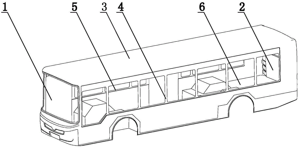
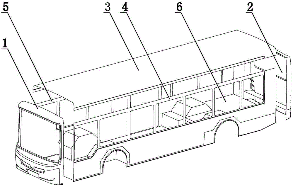
[0027] A kind of modular passenger car of present embodiment, combines figure 2 and image 3 As shown, it is composed of a front wall module 1, a rear wall module 2, a top cover module 3, a left wall module 4, a right wall module 5 and a floor module 6, and the left wall module 4 and the right wall module 5 pass through The top cover module 4 is connected to the floor module 6, and one end of the quasi-rectangular cylindrical structure formed by the left side wall module 4, the top cover module 3, the right side wall module 5 and the floor module 6 is connected with the front wall module 1, and the other One end is connected to the rear wall module 2, and between the front wall module 1 and the top cover module 3, between the front wall module 1 and the left wall module 4, between the front wall module 1 and the right wall module 5, and between the front wall module Between module 1 and floor module 6, between rear wall module 2 and left wall module 4, between rear wall modu...

Embodiment 2

[0033] The setting and working principle of this embodiment are the same as that of Embodiment 1, the difference lies in: combining Figure 5 , the connector 7 is composed of a section one 71, a section two 72 and a zigzag connecting layer 73 and a reinforcing rib 74. It is connected by a zigzag connection layer 73, and the zigzag connection layer 73 passes through the gap between the first section 71 and the second section 72 from the outer wall of the top cover module 3 where section one 71 is located, and then extends to the left side surrounding module where section two 72 is located. 4 inner side walls, thus, combined with Figure 6 , a parallel zone 731 is formed on the outer wall of the module where section one 71 is located, a broken line zone 732 is formed between section one 71 and section two 72, parallel zone two 733 is formed on the inner wall of the module where section two 72 is located, parallel zone one 731 , the folding line area 732 and the first parallel a...


PUM


Abstract

The invention relates to a modular passenger car body, and belongs to the technical field of traffic facilities. The modular passenger car body comprises a front wall module, a back wall module, a top cover module, a left side wall module, a right side wall module and a floor module, wherein the left side wall module and the right side wall module are connected through the top cover module and the floor module; the front wall module and the top cover module, the front wall module and the left side wall module, the front wall module and the right side wall module, the front wall module and the and the floor module, the top cover module and the left side wall module, the top cover module and the right side wall module, the top cover module and the back wall module, the floor module and the left side wall module, the floor module and the right side wall module, the floor module and the back wall module, the back wall module and the left side wall module, the back wall module and the right side wall module are connected through connecting pieces. The modular passenger car body is applicable to passenger car assembly, and has the advantages of light weight, high strength, convenient reshaping, and the like.

Description

technical field [0001] The invention relates to a modular bus body, which belongs to the technical field of traffic facilities. Background technique [0002] At present, the common bus body structure such as figure 1 As shown, the car body is a metal skeleton structure, generally made of steel, aluminum alloy, special-shaped steel pipe and other metal materials, and then the whole car body is formed by welding and other connection methods. The advantage of this kind of body lies in its high strength and impact resistance, but its defects are also obvious: heavy weight and large inertial force; poor corrosion resistance, which is not conducive to long-term outdoor use; high cost and high price; many parts and complicated assembly processes , The assembly time is long, and once assembled, the specifications are fixed and cannot be changed flexibly. [0003] Based on this, this application is made. Contents of the invention [0004] In order to overcome the above-mentioned...

Claims


Application Information

Patent Timeline
Patent Type & Authority Applications(China)
IPC IPC(8): B62D31/02B62D29/04
Inventor 沈伟王冠戈家荣胡纪根张卉梓王建邹尚武
Owner 绍兴宝旌复合材料技术研发有限公司
Why Eureka
Try Eureka