
Lifting supporting wheel assembly and cantilever sliding door

A technology of supporting wheels and lifting wheels, which is applied in the field of translation doors, can solve problems such as loss of appearance, affecting the visual effect of suspension, and damage to the door body

Active Publication Date: 2016-01-20
JIANGXI BAISHENG GATE & DOOR AUTOMATION
View PDF12 Cites 8 Cited by
  • Summary
  • Abstract
  • Description
  • Claims
  • Application Information

AI Technical Summary

Problems solved by technology

However, when the front end of the cantilever translation door is close to the sliding support wheel, the front end of the door body does not need additional support, and the fixed support wheel will affect the suspension visual effect and damage the appearance; and in the opening or closing process of the door body, If the supporting wheels are placed on the uneven ground to support the door body, it will cause the door body to shake up and down during operation, which will easily cause damage to the door body

Method used


Image

  • Lifting supporting wheel assembly and cantilever sliding door
  • Lifting supporting wheel assembly and cantilever sliding door
  • Lifting supporting wheel assembly and cantilever sliding door

Examples


Embodiment 1

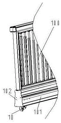
[0029] like figure 1 As shown, the cantilever translation door includes a cantilever door body 100, a translation door machine and a supporting device. The bottom beam 101 of the cantilever door body 100 is made of a multi-cavity hollow profile, and the bottom of the lower chamber of the bottom beam 101 is provided with strip-shaped openings along the length direction. The supporting device comprises two sliding supporting wheels and a lifting supporting wheel assembly 10 .

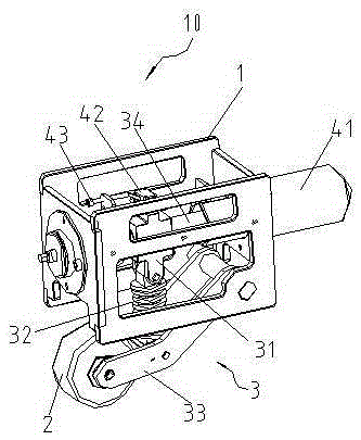
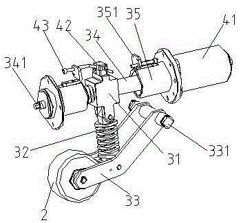
[0030] The lifting support wheel assembly 10 can be produced, transported and sold separately; it can be conveniently installed on the front end of the cantilever door body 100 during use, that is, the end away from the sliding support wheel, and then sealed in the bottom beam 101 by the side cover 102 . like figure 2 As shown, the lifting support wheel assembly 10 includes a box body 1, a lifting wheel 2, a slider crank mechanism 3, a driving mechanism and a power supply mechanism.

[0031] The box ...

Embodiment 2

[0050] In the second embodiment, except that the elastic connecting rod is replaced with a rigid structure, other structures are the same as in the first embodiment. For the same structures as those in the first embodiment, the second embodiment uses the same numbers.

[0051] like Figure 9 As shown, the connecting rod 36 is a rigid rod-like structure.

[0052] If the length of the cantilever door body 100 is short, since the front end of the door body is closer to the sliding support wheel during operation, it is not easy to sag and deform, so it is not necessary to let the lifting wheel 2 move against the ground when the door body is opened or closed. , so that the lifting wheel 2 can be raised when the door body is about to be opened, or the lifting wheel 2 is put down when it is closed in place, although the rigid connecting rod 36 does not have a buffering effect, it will not affect the smooth operation of the door body. In addition, if the lifting wheel 2 moves agains...

Embodiment 3

[0054] In the third embodiment, except that the elastic connecting rod is replaced with a rigid structure; and the single lifting wheel is replaced with a double-wheel structure, and the shapes of the connecting rod and the crank are adjusted accordingly, other structures are the same as in the first embodiment. For the same structures as those in the first embodiment, the third embodiment uses the same numbers.

[0055] like Figure 10 As shown, there are two lifting wheels 6, which are connected together by the lifting wheel shaft 61, and are more stable when supported on the ground.

[0056] The connecting rod 37 is a rigid flat rod-shaped structure, and its upper end is hinged on the lower end of the slide block 31 , and the lower end of the connecting rod 37 is hinged with the middle part of the lifting wheel shaft 61 . The crank 38 is in the shape of a curved arm with an obtuse upper and lower portion. The upper end of the crank 38 is rotatably sleeved on the crank sha...


PUM


Abstract

The invention relates to a lifting supporting wheel assembly and a cantilever sliding door, and belongs to the technical field of sliding doors. The lifting supporting wheel assembly is characterized by comprising a case, a slider-crank mechanism, a drive mechanism and a lifting wheel; the case is a hollow cavity with an opening in the bottom face, and a guide rod is transversely arranged in the case; the slider-crank mechanism comprises a slider, a crank and a connecting rod connecting the slider and the crank through two rotating pairs; the slider is arranged on the guide rod in a sliding and sleeving manner, the upper portion of the crank is rotationally connected to the case, and the lower portion of the crank is hinged to the lifting wheel; and the drive mechanism is used for driving the slider to slide. Compared with the prior art, the lifting supporting wheel assembly and the cantilever sliding door have the following beneficial effects that the slider-crank mechanism can be driven by the drive mechanism to run, and meanwhile the lifting wheel is driven to ascend and descend. When the lifting wheel abuts against the ground, a cantilever door body can be prevented from hanging down and deforming. Meanwhile, the lifting wheel can be folded upwards and hung above the ground, the suspension vision effect of the cantilever door body cannot be affected, or stable running of the door body cannot be hindered.

Description

technical field [0001] The invention relates to a lifting support wheel assembly and a cantilever translation door, belonging to the technical field of translation doors. Background technique [0002] The cantilever translational door is provided with two sliding support wheels at the rear end of the door body, and the two sliding support wheels are fixed on the ground with an appropriate distance apart to suspend the cantilever door body above the ground. The bottom beam of the door body is a hollow structure, and the bottom is provided with strip-shaped openings along the length direction. The two sliding support wheels pass through the strip-shaped opening of the bottom beam, and form a friction transmission with the inner cavity of the bottom beam, so that the cantilever door body can be suspended and translated in the air when it is opened or closed. After the cantilever door body is closed in place, the front end of the door body away from the sliding support wheels i...

Claims


Application Information

Patent Timeline
Patent Type & Authority Applications(China)
IPC IPC(8): E05D13/00E06B11/02
CPCY02T10/70
Inventor 刘润根
Owner JIANGXI BAISHENG GATE & DOOR AUTOMATION
Learn More