
Grouting monitoring system and monitoring method thereof

A monitoring system and grouting technology, which is applied to the automatic control system of drilling, earthwork drilling, drilling equipment, etc., can solve the problems that the quality and safety of grouting cannot be guaranteed, and achieve the guarantee of construction safety, construction quality, and good grouting The effect of the slurry effect

Inactive Publication Date: 2016-01-20
CHINA HUAYE GROUP
View PDF9 Cites 7 Cited by
  • Summary
  • Abstract
  • Description
  • Claims
  • Application Information

AI Technical Summary

Problems solved by technology

[0005] In view of the above problems, the purpose of the present invention is to provide a grouting monitoring system and its monitoring method to solve the problem that only the grouting parameter information at a certain point in time can be obtained in the current grouting process, and the quality and safety of the grouting cannot be obtained. Guarantee and other issues

Method used


Image

  • Grouting monitoring system and monitoring method thereof
  • Grouting monitoring system and monitoring method thereof
  • Grouting monitoring system and monitoring method thereof

Examples


Embodiment Construction

[0020] In the following description, for purposes of explanation, numerous specific details are set forth in order to provide a thorough understanding of one or more embodiments. It may be evident, however, that these embodiments may be practiced without these specific details. In other instances, well-known structures and devices are shown in block diagram form in order to facilitate describing one or more embodiments.

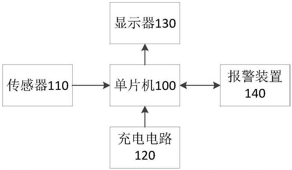
[0021] specifically, figure 1 The logical structure of the grouting monitoring system according to the embodiment of the present invention is shown.

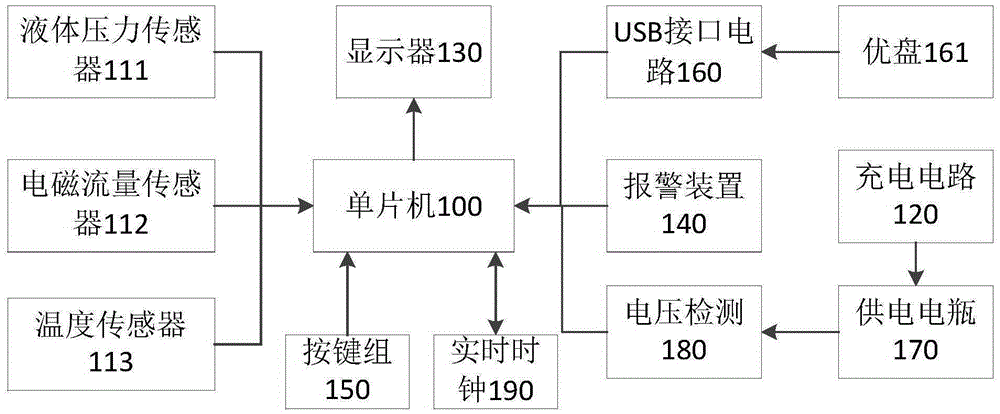
[0022] Such as figure 1 As shown, the grouting monitoring system of the embodiment of the present invention includes a single-chip microcomputer 100 , sensors 110 connected to the single-chip microcomputer 100 , a display 130 , an alarm device 140 and a charging circuit 120 for supplying power to the single-chip microcomputer 100 . Wherein, each data information of parameters such as the actual pressure of t...


PUM


Abstract

The invention provides a grouting monitoring system and a monitoring method thereof. The grouting monitoring system comprises a single-chip microcomputer, a sensor, a displayer, an alarm device and a charging circuit, wherein the sensor, the displayer and the alarm device are connected with the single-chip microcomputer, and the charging circuit is used for charging the single-chip microcomputer; the sensor is used for collecting data information of actual pressure at an outlet of a grouting pump as well as instantaneous flow and cumulative flow of the grouting pump; the single-chip microcomputer processes all data information collected by the sensor, and the data information is displayed through the displayer; the alarm device is used for giving an alarm when all data collected by the sensor exceed corresponding preset thresholds. By the adoption of the grouting monitoring system, dynamic changes in grouting pressure and flow can be monitored in real time, and danger can be warned in time.

Description

technical field [0001] The invention relates to the field of grouting, and more specifically, to a grouting monitoring system and a monitoring method for grouting in mines and rocks. Background technique [0002] Traditional grouting in the working face of the wellbore usually uses mechanical pressure gauges and flow meters, which can only observe the grouting parameter information at a certain point in time. When the grouting pressure rises for a short time and continues to be in a high It is very easy to cause high pressure to damage the grouting pipeline and other accidents. [0003] In addition, real-time data such as pressure and flow during the grouting process can feed back the geological information of the grouting formation in real time, and serve as a reliable reference for dynamic adjustment of grouting. have played a very important role. [0004] Therefore, there is an urgent need for a grouting monitoring system that can grasp the dynamic parameters in the gro...

Claims


Application Information

Patent Timeline
IPC IPC(8): E21B44/06
Inventor 何磊张浩王志军
Owner CHINA HUAYE GROUP
Learn More