Pneumatic pump for condensate recovery
A technology for pneumatic pumps and condensed water, applied to pumps, pump components, pump control, etc., can solve problems such as inconvenient maintenance, complex structure, and low delivery efficiency
- Summary
- Abstract
- Description
- Claims
- Application Information
AI Technical Summary
Problems solved by technology
Method used
Image

Examples
Embodiment 1
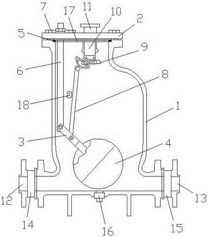
[0018] refer to figure 1 As shown, a pneumatic pump for condensate recovery includes a pump body 1, a pump cover 2, a support rod 3 and a floating ball 4. The pump cover 2 is arranged on the pump body 1, and the pump cover 2 is fixed to the pump body 1. connection, a gasket 5 is provided between the pump cover 2 and the pump body 1, the strut 3 and the floating ball 4 are set in the pump body 1, the strut 3 is set on the floating ball 4, and the strut 3 is fixedly connected with the floating ball 4, the pump body 1 is also provided with a pillar 6, the top of the pillar 6 is provided with a fixing nut 7, and the pillar 6 is fixedly connected with the pump cover 2 through the fixing nut 7, and the pillar 6 Hinged with the pole 3, the middle part of the pole 3 is provided with a connecting rod 8, the connecting rod 8 is hinged with the pole 3, the end of the connecting rod 8 is provided with a spring 9 and an air valve 10, and the connecting rod 8 passes through the spring 9 is...
Embodiment 2
[0027] refer to figure 1 As shown, a pneumatic pump for condensate recovery includes a pump body 1, a pump cover 2, a support rod 3 and a floating ball 4. The pump cover 2 is arranged on the pump body 1, and the pump cover 2 is fixed to the pump body 1. connection, a gasket 5 is provided between the pump cover 2 and the pump body 1, the strut 3 and the floating ball 4 are set in the pump body 1, the strut 3 is set on the floating ball 4, and the strut 3 is fixedly connected with the floating ball 4, the pump body 1 is also provided with a pillar 6, the top of the pillar 6 is provided with a fixing nut 7, and the pillar 6 is fixedly connected with the pump cover 2 through the fixing nut 7, and the pillar 6 Hinged with the pole 3, the middle part of the pole 3 is provided with a connecting rod 8, the connecting rod 8 is hinged with the pole 3, the end of the connecting rod 8 is provided with a spring 9 and an air valve 10, and the connecting rod 8 passes through the spring 9 is...
Embodiment 3
[0036] refer to figure 1As shown, a pneumatic pump for condensate recovery includes a pump body 1, a pump cover 2, a support rod 3 and a floating ball 4. The pump cover 2 is arranged on the pump body 1, and the pump cover 2 is fixed to the pump body 1. connection, a gasket 5 is provided between the pump cover 2 and the pump body 1, the strut 3 and the floating ball 4 are set in the pump body 1, the strut 3 is set on the floating ball 4, and the strut 3 is fixedly connected with the floating ball 4, the pump body 1 is also provided with a pillar 6, the top of the pillar 6 is provided with a fixing nut 7, and the pillar 6 is fixedly connected with the pump cover 2 through the fixing nut 7, and the pillar 6 Hinged with the pole 3, the middle part of the pole 3 is provided with a connecting rod 8, the connecting rod 8 is hinged with the pole 3, the end of the connecting rod 8 is provided with a spring 9 and an air valve 10, and the connecting rod 8 passes through the spring 9 is ...
PUM
 Abstract
Description
Claims
Application Information
 - R&D Engineer
- R&D Manager
- IP Professional
- Industry Leading Data Capabilities
- Powerful AI technology
- Patent DNA Extraction
Browse by: Latest US Patents, China's latest patents, Technical Efficacy Thesaurus, Application Domain, Technology Topic.
© 2024 PatSnap. All rights reserved.Legal|Privacy policy|Modern Slavery Act Transparency Statement|Sitemap