
Peristaltic pump

A peristaltic pump and driver technology, applied in the field of peristaltic pumps, can solve problems such as peristaltic pump cavity erosion and increase maintenance costs, and achieve the effects of reducing failure rates, reducing maintenance costs, and improving purity

Inactive Publication Date: 2016-01-20
GUANGDONG WEICHUANG TECH DEV
View PDF4 Cites 4 Cited by
  • Summary
  • Abstract
  • Description
  • Claims
  • Application Information

AI Technical Summary

Problems solved by technology

[0004] The purpose of the present invention is to provide a peristaltic pump to solve the technical problem that the cavity of the peristaltic pump is corroded in the prior art, thereby increasing the maintenance cost

Method used


Image

  • Peristaltic pump
  • Peristaltic pump
  • Peristaltic pump

Examples


Embodiment Construction

[0035] The technical solutions of the present invention will be clearly and completely described below in conjunction with the accompanying drawings. Apparently, the described embodiments are some of the embodiments of the present invention, but not all of them. Based on the embodiments of the present invention, all other embodiments obtained by persons of ordinary skill in the art without making creative efforts belong to the protection scope of the present invention.

[0036] In the description of the present invention, it should be noted that the terms "center", "upper", "lower", "left", "right", "vertical", "horizontal", "inner", "outer" etc. The indicated orientation or positional relationship is based on the orientation or positional relationship shown in the drawings, and is only for the convenience of describing the present invention and simplifying the description, rather than indicating or implying that the referred device or element must have a specific orientation, ...


PUM


Abstract

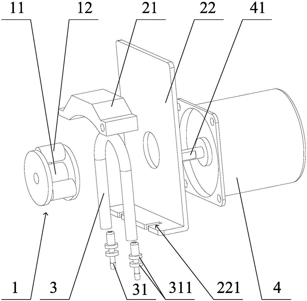
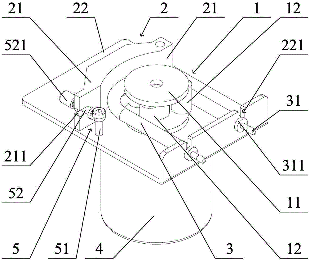
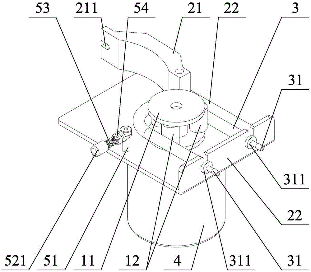
The invention relates to the technical field of fluid pumping and injection and provides a peristaltic pump. The peristaltic pump comprises a hose, a driver, a limiting part and a rotary squeezing part, wherein the driver is arranged on the limiting part; an output shaft of the driver is connected with the rotary squeezing part and used for driving the rotary squeezing part to rotate; the hose is arranged on the rotary squeezing part in an eracting manner, and the position of the rotary squeezing part is fixed through the limiting part. The rotary squeezing part squeezes and pushes the hose by rotation, and therefore pumping and injection of fluid are realized. By adopting the structure, the fluid is guided through the hose and makes no contact with a pump body, and therefore the fluid does not corrode the peristaltic pump. The failure rate of the peristaltic pump is lowered, repairing expenses are reduced, and the fluid is not polluted and keeps batter purity.

Description

technical field [0001] The invention relates to the technical field of fluid pumping, in particular to a peristaltic pump. Background technique [0002] In industries such as chemical industry, food and environmental protection monitoring, peristaltic pumps are often used for pumping fluid; the peristaltic pumps in the prior art are provided with a sealed cavity inside the pump body, and the cavity is used to carry out the fluid in the pump body. The circulation channel, that is, the fluid entering the pump body will pass through the sealed cavity, and then be injected into the subsequent process flow. [0003] In the prior art, if the fluid to be pumped is highly corrosive, acidic or alkaline, then when the fluid enters the sealed cavity, it will corrode the side wall of the cavity and the fittings in the cavity, thus damaging the peristaltic pump, resulting in higher maintenance costs. Contents of the invention [0004] The object of the present invention is to provide...

Claims


Application Information

Patent Timeline
Patent Type & Authority Applications(China)
IPC IPC(8): F04B43/12
Inventor 陈青陈天渝李汉汉李泽彪朱润泉
Owner GUANGDONG WEICHUANG TECH DEV
Learn More