Supercharge Your Innovation With Domain-Expert AI Agents!

Oil-gas separation system for oil injection screw vacuum pump

A screw vacuum pump and separation system technology, which is applied to the components of the pumping device for elastic fluid, pump components, rotary piston type/swing piston type pump components, etc., can solve the problem of high equipment maintenance cost and reduce maintenance. Cost, reduced requirements, small size effect

Active Publication Date: 2016-01-20
无锡锡压压缩机有限公司
View PDF8 Cites 0 Cited by
  • Summary
  • Abstract
  • Description
  • Claims
  • Application Information

AI Technical Summary

Problems solved by technology

[0003] In view of the above problems, the present invention provides an oil-gas separation system for oil-injected screw vacuum pumps, which can solve the problem of high equipment maintenance costs in the first-stage fine separator used in existing oil-injected screw vacuum pumps

Method used


Image

  • Oil-gas separation system for oil injection screw vacuum pump
  • Oil-gas separation system for oil injection screw vacuum pump
  • Oil-gas separation system for oil injection screw vacuum pump

Examples


Embodiment Construction

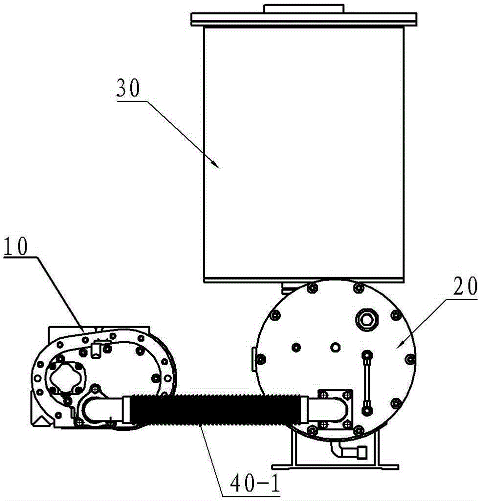
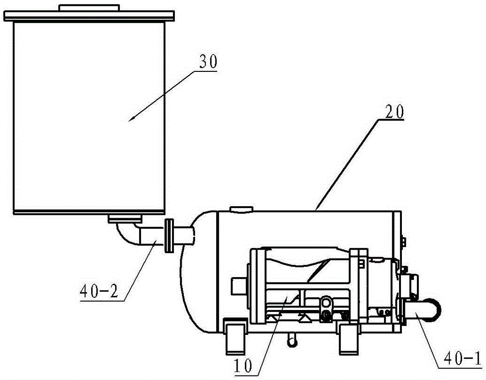
[0022] See figure 1 and figure 2 , the present invention is used for the oil-gas separation system of an oil-injected screw vacuum pump, which includes an oil-injected screw vacuum pump host 10 and a fine separator 30, and a rough separator 20 is also arranged between the oil-injected screw vacuum pump host 10 and the fine separator 30, The oil-injected screw vacuum pump 10 , the rough separator 20 and the fine separator 30 are respectively connected through exhaust connecting pipes 40 in sequence.

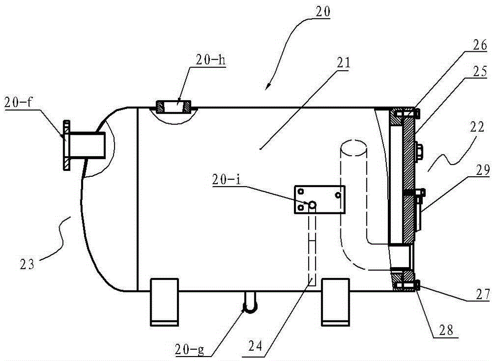
[0023] Wherein, the coarse separator 20 comprises a coarse separator cylinder 21, see image 3 and Figure 4 , the two sides of the coarse separator cylinder 21 are respectively the coarse air inlet end 22 sealed by the end cover 25 and the coarse exhaust outlet end 23 integrally provided with the coarse separator cylinder 21, wherein the end cover 25 It is sealed with the coarse separator cylinder 21 by an O-ring 26 and fixed by bolts 27 and gaskets 28; the coarse air inlet e...


PUM


Abstract

The invention provides an oil-gas separation system for an oil injection screw vacuum pump. The problem of high equipment maintaining cost of a first-level fine separator used in an existing oil injection screw vacuum pump can be solved. The oil-gas separation system for the oil injection screw vacuum pump comprises a main machine of the oil injection screw vacuum pump and a fine separator and is characterized in that a rough separator is arranged between the main machine of the oil injection screw vacuum pump and the fine separator, and the oil injection screw vacuum pump, the rough separator and the fine separator are sequentially connected through exhausting coupling pipes.

Description

technical field [0001] The invention relates to the technical field of oil-gas separation, in particular to the technical field of oil-gas separation of oil-injected screw vacuum pumps, in particular to an oil-gas separation system for oil-injected screw vacuum pumps. Background technique [0002] Most of the existing oil-injected screw vacuum pumps use a first-stage oil-gas separator, that is, an oil-gas fine separator is directly installed at the rear end of the oil-injected screw vacuum pump host to realize oil-gas separation. The filter element and the seal are assembled. The oil-gas mixture discharged from the main engine enters the cylinder tangentially along the cylinder of the oil-gas fine separator. The oil-gas mixture hits the inner wall of the cylinder in the cylinder, and is initially separated by cyclone and sedimentation, and then the mixed oil and gas are re- After being adsorbed and separated by the oil-gas separation filter element, it is discharged from the...

Claims


Application Information

Patent Timeline
Patent Type & Authority Applications(China)
IPC IPC(8): F04C29/02
Inventor 孙凯朱峰刘建军
Owner 无锡锡压压缩机有限公司
Features
  • R&D
  • Intellectual Property
  • Life Sciences
  • Materials
  • Tech Scout
  • Unparalleled Data Quality
  • Higher Quality Content
  • 60% Fewer Hallucinations
Learn More