
Wind pipe machine

A duct machine and duct temperature technology, applied in the field of air conditioners, can solve the problems affecting the application range of products, troubles for maintenance personnel, single wiring holes, etc., and achieve the effects of improving product convenience, wide application range, and improving production efficiency.

Active Publication Date: 2016-01-20
GD MIDEA AIR-CONDITIONING EQUIP CO LTD +1
View PDF6 Cites 2 Cited by
  • Summary
  • Abstract
  • Description
  • Claims
  • Application Information

AI Technical Summary

Problems solved by technology

Because the traditional air duct indoor unit pipe pressure plate structure only considers the leakage of cold air at the input and output pipes and only plays a pressing role, the middle beam and the electric control box are not designed with wiring holes, or the wiring holes are single, which is not conducive to wiring and dismantling. It also causes trouble for market maintenance personnel
Therefore, when maintaining the traditional air duct machine, the top cover and the water tray must be removed. If the pipe temperature sensor needs to be replaced, the side panels and the rear cover need to be removed to make room for maintenance, so as to pull out the pipe temperature line. , this structure undoubtedly requires a large and specific installation site that is conducive to maintenance, that is, there are special requirements for the installation environment of the product, which affects the application range of the product

Method used


Image

  • Wind pipe machine
  • Wind pipe machine
  • Wind pipe machine

Examples


Embodiment Construction

[0037] In order to understand the above-mentioned purpose, features and advantages of the present invention more clearly, the present invention will be further described in detail below in conjunction with the accompanying drawings and specific embodiments. It should be noted that, in the case of no conflict, the embodiments of the present application and the features in the embodiments can be combined with each other.

[0038] In the following description, many specific details are set forth in order to fully understand the present invention. However, the present invention can also be implemented in other ways different from those described here. Therefore, the protection scope of the present invention is not limited by the specific details disclosed below. EXAMPLE LIMITATIONS.

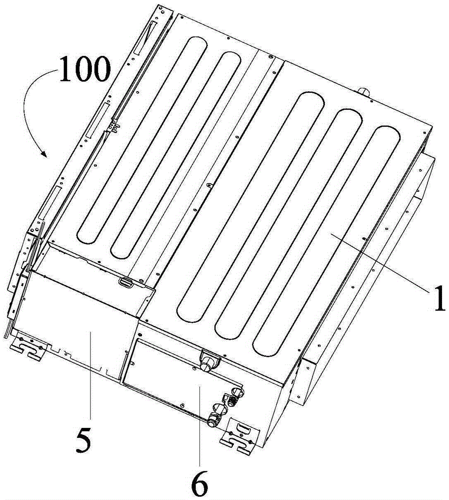
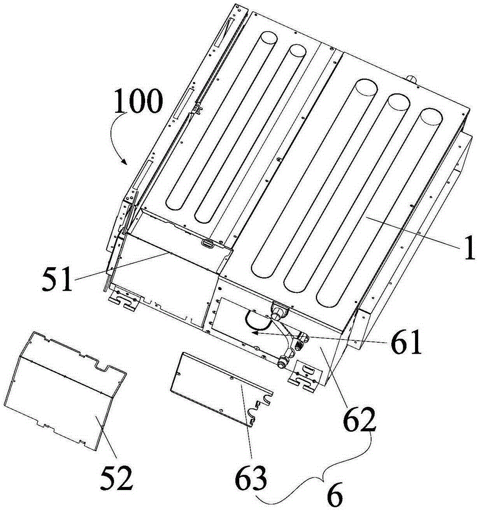
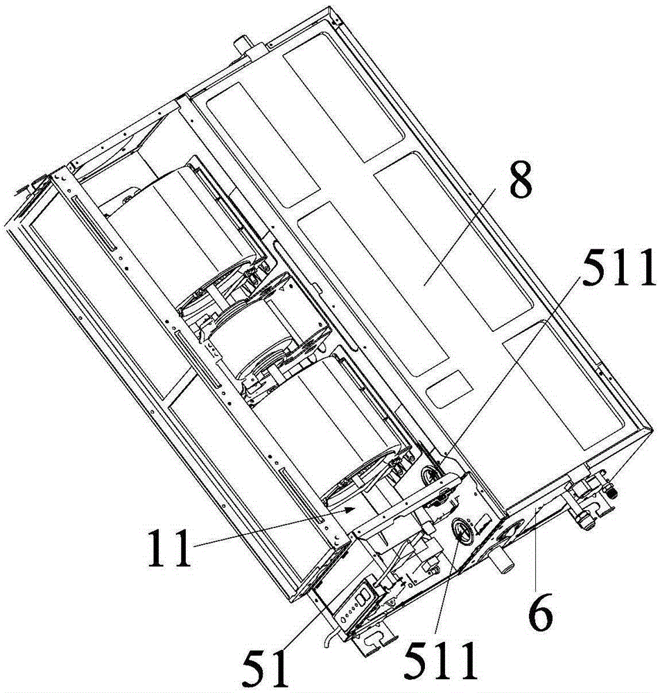
[0039] Refer below Figure 1 to Figure 7 The duct machine according to some embodiments of the present invention is described.

[0040] Such as Figure 1 to Figure 4 As shown, the air duct machine...


PUM


Abstract

The invention provides a wind pipe machine. The wind pipe machine comprises a shell body and a side plate assembly. An installation cavity is formed by the shell body in an enclosed mode. One end of the installation cavity is provided with an opening. An air channel air outlet, a heat exchanger, a pipe temperature sensor and an electric control box assembly are arranged in the installation cavity. The side plate assembly is arranged at the opening of the installation cavity and closes the of the installation cavity. The side plate assembly is provided with a universal maintenance opening. The air channel air outlet, the heat exchanger and the pipe temperature sensor can be examined through the maintenance opening, and the pipe temperature sensor is maintained or replaced. According to the a wind pipe machine, the side plate assembly is arranged at the opening of the installation cavity and closes the of the installation cavity; the air channel air outlet, the heat exchanger and the pipe temperature sensor can be examined through the maintenance opening in the side plate assembly, and the pipe temperature sensor is maintained or replaced, so that the traditional conditions that maintenance is conducted by detaching a top cover and a water-containing disk are avoided, and accordingly the pipe temperature sensor is maintained or replaced conveniently and simply, and the installation-maintenance efficiency of the product is improved. Therefore, the production efficiency of the product is improved. The occupying space is small. The application range of installation sites is wide.

Description

technical field [0001] The invention relates to the technical field of air conditioning, in particular to an air duct machine. Background technique [0002] At present, the maintenance of the drainage pump of the air duct machine, the maintenance of the indoor pipe temperature sensor and the direction of the electric control line have always been difficult problems for the maintenance personnel in the air duct machine market. Because the traditional air duct indoor unit pipe pressure plate structure only considers the leakage of cold air at the input and output pipes and only plays a pressing role, the middle beam and the electric control box are not designed with wiring holes, or the wiring holes are single, which is not conducive to wiring and dismantling. Also cause trouble to the maintenance personnel of the market. Therefore, when maintaining the traditional air duct machine, the top cover and the water tray must be removed. If the pipe temperature sensor needs to be r...

Claims


Application Information

Patent Timeline
Patent Type & Authority Applications(China)
IPC IPC(8): F24F1/00F24F13/00F24F13/22
CPCF24F1/0007F24F13/00F24F13/22
Inventor 廖志平陆飞龙
Owner GD MIDEA AIR-CONDITIONING EQUIP CO LTD
Learn More