

Large-dynamic-range omnibearing sample BRDF (bidirectional reflectance distribution function) measuring device
A technology with a large dynamic range and a measuring device, which is applied in the measurement of scattering characteristics, etc., can solve the problems of difficult to achieve a large dynamic range measurement, few design solutions for the device, and limited sensitivity of the detector, so as to facilitate the calculation of azimuth and astronomical angle. Top angle, large dynamic measurement range, convenient test effect
- Summary
- Abstract
- Description
- Claims
- Application Information
AI Technical Summary
Problems solved by technology
Method used
Image

Examples
Embodiment 2
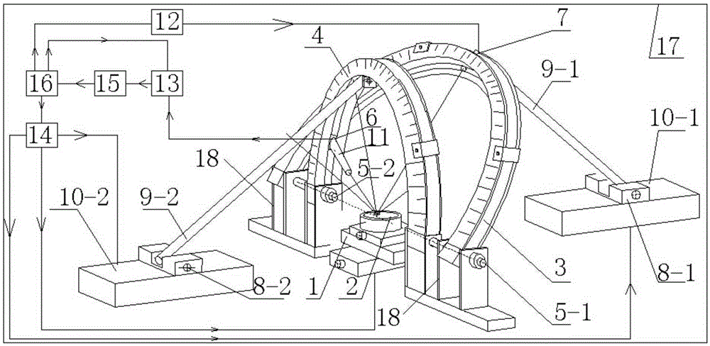
[0045] Embodiment 2: On the basis of Embodiment 1, a filter can be installed at the front end of the light guide 11, and the inner wall of the light guide 11 is blackened, and the scattered light on the surface of the sample enters the detector through the light guide and the filter On the one hand, the setting of the light pipe avoids the impact of space stray light incident on the detector on the one hand, and on the other hand avoids the impact of dust and other particles on the incident light path on the measurement, and the filter only allows a certain wavelength range The light incident on the detector greatly improves the signal-to-noise ratio of the measurement.
Embodiment 3
[0046] Embodiment 3: The difference with Embodiment 1 is: the detector modules can be covered with on the detector track, and the lock-in amplifier module and the data acquisition channel can be increased accordingly, and the measurement signal can be similarly acquired synchronously and adjusted the magnification , which can realize multi-point synchronous measurement and improve measurement efficiency.
Embodiment 4
[0047] Embodiment 4: On the basis of Embodiment 1: For the measurement of the incident light power of the light source, the sample can be replaced by a total reflection mirror, and the incident angle and azimuth angle of the incident light are adjusted to a certain position, such as the zenith angle is set to -30°, the azimuth angle is 90°, and temporarily remove the photomultiplier tube (to avoid strong light damage), and add an attenuation sheet to the front end of the light guide 11 to attenuate the light energy to the detection range of the photodiode. The zenith angle of the module is set to 30°, and the azimuth angle is 270°, that is, let the reflected light enter the photodiode for detection to obtain the radiant flux of the incident reference light, which is convenient for calculating the BRDF (Note: you can use the rotation axis 5-1 and the rotation axis 2 5 The line connecting the axes of -2 forms the X axis, and the direction of the X axis is defined as pointing from...
PUM
 Abstract
Description
Claims
Application Information