
Common optical path multiple inclined wave surface compensation non-zero position interferometry device

A technology of interferometry and oblique waves, which is applied in the direction of measuring devices, optical devices, instruments, etc., can solve the problems of high-quality and large-diameter beam-splitting prisms, the difficulty of processing and manufacturing, increasing the cost of processing and installation, and the inability to achieve measurement, etc., to achieve a huge industry Potential for optimization, expansion of dynamic measurement range, and ease of engineering application

Active Publication Date: 2016-01-20
NANJING UNIV OF SCI & TECH
View PDF9 Cites 2 Cited by
  • Summary
  • Abstract
  • Description
  • Claims
  • Application Information

AI Technical Summary

Problems solved by technology

Due to the use of a dual optical path structure and no common optical path characteristics, the system error increases. In order to ensure the measurement accuracy and compensate for the increase in the system error, higher requirements must be placed on the processing of the device, which increases the cost of processing and installation.
In addition, the measurement of optical free-form surfaces of large diameters requires the manufacture of beamsplitters of corresponding diameters, and the processing and manufacture of high-quality large-diameter beamsplitters is very difficult.
This means that the measurement of large-aperture optical free-form surfaces cannot be realized with this device

Method used


Image

  • Common optical path multiple inclined wave surface compensation non-zero position interferometry device

Examples


Embodiment Construction

[0012] The present invention will be described in further detail below in conjunction with the accompanying drawings.

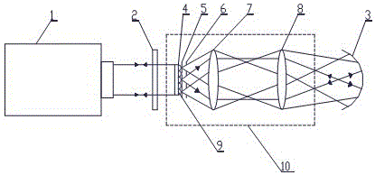
[0013] combine figure 1 , the common optical path multiple inclined wave surface compensation non-zero position interferometry device is composed of a Fizeau interferometer 1, a standard flat crystal 2, a free-form surface gradient compensation module 10 and a free-form surface to be measured 3, the main optical axis of the free-form surface gradient compensation module 10 It coincides with the main optical axis formed by the Fizeau interferometer 1, the standard flat crystal 2 and the free-form surface 3 to be measured. The main optical axis of the device constitutes the main optical axis of the interferometry device, wherein the free-form surface gradient compensation module 10 includes a microlens array 4, a pinhole array 5, a dynamic mask 6, a collimating objective lens 7 and a standard lens 8, and the microlens array 4 is located in the parallel optical...


PUM


Abstract

The invention discloses a common-light-path type multiple inclined wave surface compensation nonzero-digit interference measurement device which comprises a Fizeau interferometer, a standard optical flat, a free-form surface gradient compensation module and a free-form surface to be measured. A primary optical axis of the free-form surface gradient compensation module coincides with a primary optical axis of the interference measurement device, a parallel light beam emitted by the Fizeau interferometer passes through the standard optical flat and is divided into two light beams, one light beam is reflected by the surface of the standard optical flat back to the Fizeau interferometer to be used as reference light, the other light beam enters in the free-form surface gradient compensation module and is emitted out of the free-form surface gradient compensation module, and testing light beams with different inclined angles are formed to irradiate the free-form surface to be measured in an incident mode, are reflected by the free-form surface to be measured back to the free-form surface gradient compensation module, finally are emitted out of the free-form surface gradient compensation module and return to the Fizeau interferometer to form test light. According to the test, high-precision measurement on the optical free-form surface large in local gradient and transportability modularization on the measurement device are achieved simultaneously.

Description

technical field [0001] The invention belongs to the field of optical precision measurement, and relates to a device for measuring optical free-form surfaces. Background technique [0002] In the design and manufacture process of traditional large-scale optical systems, in order to obtain better optical quality, some larger-caliber optical components are often used. These optical components are bulky, difficult to manufacture, high in cost, and their surface quality is affected by the environment and stress. Great impact. The optical free-form surface can not only obtain better optical quality than traditional optical surfaces, but also greatly reduce the volume size of optical components, and has the advantages of light weight, convenient installation and adjustment, and low cost. Optical free-form surfaces have been widely used in different fields such as astronomical observation and national defense weapons. However, the measurement level of the optical free-form surface...

Claims


Application Information

Patent Timeline
Patent Type & Authority Patents(China)
IPC IPC(8): G01B11/24
Inventor 沈华朱日宏陈磊何勇王青荣四海李建欣
Owner NANJING UNIV OF SCI & TECH
Learn More