
Variable diameter micro optical fiber ring based optical micromechanical acceleration sensor and its method

An acceleration sensor, micro-fiber technology, applied in the direction of measurement of acceleration, speed/acceleration/impact measurement, instruments, etc., can solve the problems of difficult optical fiber end face coating process, expensive processing and testing instruments, poor parallelism of optical fiber end face, etc. Dynamic measurement range, the effect of improving measurement accuracy and stability

Inactive Publication Date: 2009-02-04
ZHEJIANG UNIV
View PDF10 Cites 2 Cited by
  • Summary
  • Abstract
  • Description
  • Claims
  • Application Information

AI Technical Summary

Problems solved by technology

[0003] In existing reports, fiber optic micromechanical acceleration sensors mostly use ordinary optical fibers to measure light intensity changes caused by external acceleration changes. However, the lack of anti-interference ability of light intensity measurement restricts the practical application of such sensors. The problem of poor anti-interference ability of light intensity measurement, there has been an acceleration sensor that uses ordinary optical fiber end face reflection to form a fabry-perot cavity. The coating process is difficult, and the poor parallelism of the fiber end face and low coupling efficiency have become difficult problems to solve; in the latest international research on optical micro-mechanical acceleration sensors, micro-mechanical technology is used to fabricate optical fabry-perot cavities , this kind of micro-resonator-type acceleration sensor is superior to the fiber-end fabry-perot cavity type in terms of integration and coupling efficiency, but it has a considerable difference in the processing technology of the reflective surface coating of the micro-resonator cavity and the plane roughness of the cavity wall. It is very difficult, the required processing and testing instruments are also very expensive, and the dynamic range of this type of micro-resonator sensor measurement is very small, it is difficult to meet the requirements of practical applications

Method used


Image

  • Variable diameter micro optical fiber ring based optical micromechanical acceleration sensor and its method
  • Variable diameter micro optical fiber ring based optical micromechanical acceleration sensor and its method
  • Variable diameter micro optical fiber ring based optical micromechanical acceleration sensor and its method

Examples


Embodiment

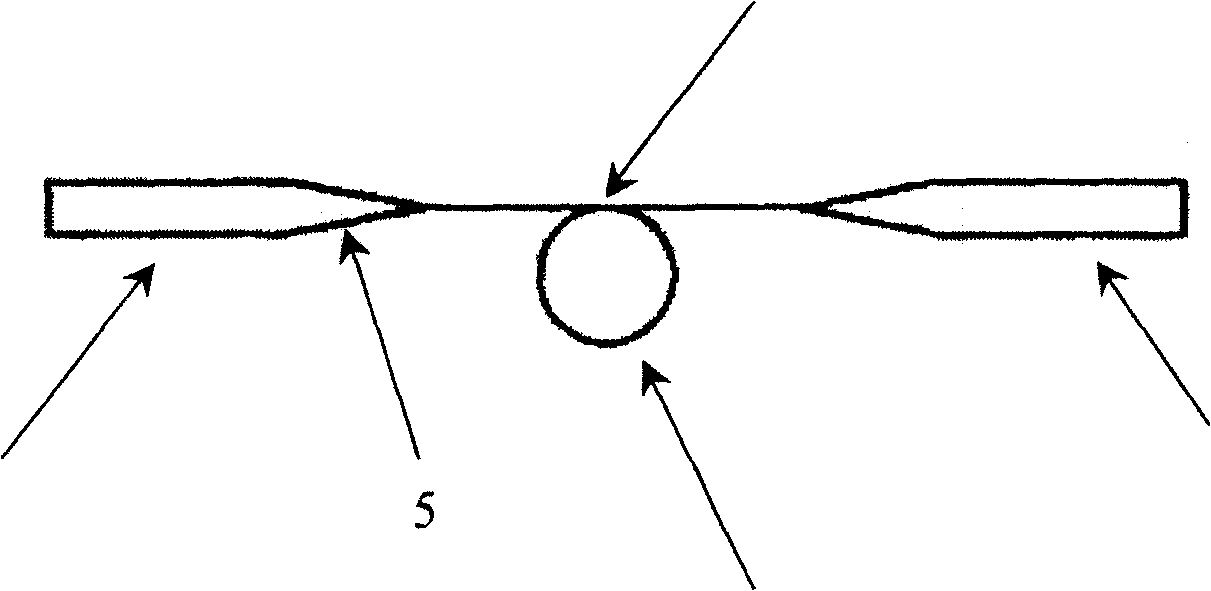
[0034] A standard single-mode optical fiber with a diameter of 125 microns is removed from the coating layer, and the single-mode optical fiber is heated by laser irradiation to draw a micro-fiber with a diameter of 5 microns, which includes a standard optical fiber, a transition zone and a micro-fiber. A movable mass supported by an elastic micro-cantilever beam with a V-shaped groove and a fixed frame connected to it are processed by photolithography and wet etching, and a V-shaped groove and a fixed frame are also carved on the fixed silicon substrate. The structure of the circular groove, and a layer of magnesium fluoride film with a thickness of 0.5 microns is coated on the contact surface of the mass block, the silicon substrate and the micro-fiber, and the fixed frame connecting the movable mass block and the fixed silicon substrate are integrated in the same on the substrate. The two micro-fibers in the coupling area of ​​the micro-fiber ring are axially parallel, and ...


PUM


Abstract

The invention discloses a variable diameter microfiber ring based optical micromechanical acceleration sensor and method thereof, which uses diameter variable ring produced by a microfiber with a diameter of 1~25 micron drawed in a standard single-mode fiber by laser heating taper-drawing technique after removing the coated layer of fiber. The microfiber connected with the standard single-mode fiber through a graded taper transition area is disposed as a diameter variable ring, and the two microfiber of microfiber ring crossing are kept axially parallel, one of which is mounted on the movable mass block of sensing acceleration, while another is mounted on the silicon substrate. The input end of the standard single-mode fiber is connected with wide-spectrum light source, the output end is connected with the fiber spectrometer, and the sensing to acceleration is realized by using diameter variable microfiber ring as high-sensitivity sensing member. The invention is capable of improving measurement precision and stability of optical micromechanical acceleration sensor and increasing dynamic measurement range.

Description

technical field [0001] The invention relates to an optical micromechanical acceleration sensor based on a variable-diameter micro-fiber ring and a method thereof. Background technique [0002] An acceleration sensor is a sensor device that uses known detectable physical quantities to sense or indirectly measure acceleration changes. It is widely used in aerospace, missile positioning guidance, industrial manufacturing, and vehicle installations. At present, there are various acceleration sensors based on different sensing principles. In recent years, with the progress of micro-machining technology, micro-machined acceleration sensors based on this process have also been developed rapidly. Compared with conventional acceleration sensors, micro-machined acceleration sensors The sensor has significant advantages such as high integration, small size, and low power consumption. However, most of the current micro-mechanical acceleration sensors have the disadvantages of low measur...

Claims


Application Information

Patent Timeline
Patent Type & Authority Patents(China)
IPC IPC(8): G01P15/093
Inventor 吴宇杨国光
Owner ZHEJIANG UNIV
Learn More