Liquid refractive index sensing method and liquid refractive index sensing device

A liquid refractive index and refractive index technology, which is applied in the measurement of phase influence characteristics, etc., can solve the problems of small dynamic measurement range, variation, and different output characteristics of refractive index sensors, achieve high sensitivity, improve linearity, and expand linearity. The effect of the working area

Active Publication Date: 2017-07-21
QUFU NORMAL UNIV
View PDF3 Cites 1 Cited by
  • Summary
  • Abstract
  • Description
  • Claims
  • Application Information

AI Technical Summary

Problems solved by technology

Although both use the sensing mechanism that the central wavelength of PBG as the characteristic wavelength drifts with the change of the refractive index of the core filling liquid, the output characteristics of the refractive index sensors based on the combination of these two types of materials are quite different.
Although the Bragg optical fiber sensor based on the high refractive index difference cladding material has a large dynamic measurement range (1.402-1.578), its sensitivity is only 330nm / RIU (K.J.Rowland, S.Afshar V., A. Stolyarov, Y.Fink, and T.M.Monro, "Bragg waveguides with low-index liquid cores," Opt. Express, vol.20, no.1, pp.48-62, Jan.2011.); while Bragg waveguides based on low-index-difference cladding materials Although the optical fiber sensor has a sensitivity as high as 1400nm / RIU (theoretical value is about 2100nm / RIU), its dynamic measurement range is small (1.333-1.378), which is mainly due to the linear relationship between the characteristic wavelength and the refractive index of the fiber core. The range will be worse (Qu H, SkorobogatiyM. "Liquid-core low-refrative-index-contrast Bragg fiber sensor", Appl. Phys. Lett., 2011, 98:201114; H.Qu and M.Skorobogatiy, "Resonant bio-andchemical sensors using low-refractive-index-contrast liquid-core Braggfibers,"Sens.Actuators B,161(1),2012,261-268.)

Method used


Image

  • Liquid refractive index sensing method and liquid refractive index sensing device
  • Liquid refractive index sensing method and liquid refractive index sensing device
  • Liquid refractive index sensing method and liquid refractive index sensing device

Examples


Embodiment 1

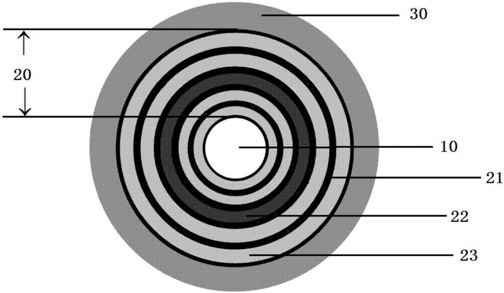
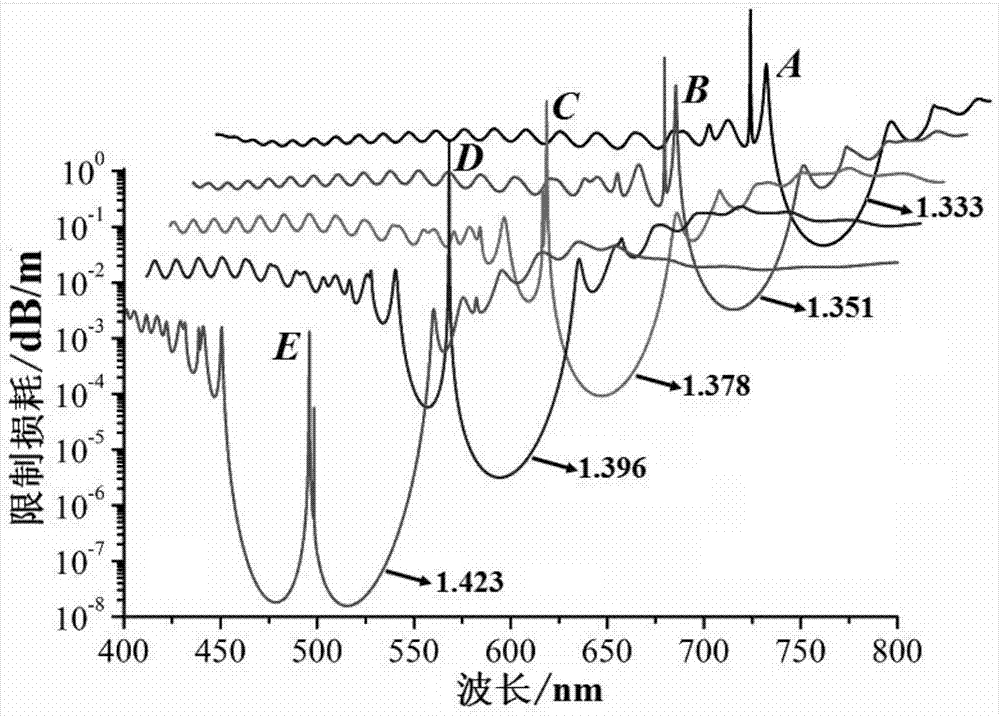
[0044] image 3 Shown is the structural parameter of the hollow Bragg optical fiber with a defect layer in the refractive index sensing device in Example 1 of the present invention is d c =800μm, N=25, n h =1.581,n l =1.487,n d =1.581,t h =130nm, t l =370nm,t d =1.2t l ,N d = 3, the refractive index of the core filling liquid n a HE at different values 11 Mode confinement loss versus wavelength. Due to the mutual coupling between the defect mode and the core mode, the HE 11 Two loss peaks, one wide and one narrow, appear in the loss spectrum of the mode, and their central wavelengths are respectively denoted by λ RW and lambda RN Indicates that below we will use λ RW (Such as image 3 A, B, C, D and E points in the center) is the characteristic wavelength λ S , to study and analyze its refractive index sensing performance. In Figure 3, A, B, C, D and E correspond to n a The characteristic wavelength λ at 1.333, 1.351, 1.378, 1.396 and 1.423 S . Depend on im...

Embodiment 2

[0045] Embodiment 2: Since the resonance wavelength in the hollow Bragg fiber containing the defect layer depends on the structural parameters of the defect layer, such as the refractive index, thickness and position of the defect layer in the cladding. Therefore, by optimizing the structural parameters of the defect layer, the λ in the liquid-filled hollow Bragg fiber sensor with a defect layer can be further improved S with n a linear correlation between them. Figure 5 The structure parameter of the hollow Bragg fiber with defect layer shown is d c =800μm, N=25, n h =1.581, n l =1.487,n d =1.68,t h =130nm,t l =370nm,t d = t l ,N d= 2, the liquid fills the λ in the hollow Bragg fiber sensor with defect layer S with n a In the figure, the abscissa x represents the liquid refractive index, and the ordinate y represents the characteristic wavelength. to lambda S with n a Linear fitting found that the linear correlation between the two was further improved (R 2 =0...


PUM

PropertyMeasurementUnit
diameteraaaaaaaaaa
refractive indexaaaaaaaaaa

Abstract

The invention relates to a liquid refractive index sensing method and a liquid refractive index sensing device. The method comprises the following steps: enabling broadband probe light to pass through a hollow Bragg fiber filled with a liquid, wherein the hollow Bragg fiber comprises a hollow fiber core, a cladding and a protective layer, the cladding is of a plurality of periodic structures, the periodic structures contain a plurality of normal periodic structures formed by a first dielectric layer and a second dielectric layer and a defected periodic structure formed by a first dielectric layer and a defect layer, the refractive index of the defect layer is greater than or equal to that of the first dielectric layer, and the refractive index of the first dielectric layer is greater than that of the second dielectric layer; obtaining the transmission spectrum of the broadband probe light passing through the hollow Bragg fiber, and then obtaining a resonant wavelength generated by mutual coupling of a defect mode and a fiber mode in the hollow Bragg fiber; using the resonant wavelength as a characteristic wavelength, and realizing the refractive index sensing of liquid to be detected based on a linear relation of the characteristic wavelength and the refractive index of the liquid to be detected. High sensitivity can be maintained, and meanwhile a relatively large liquid refractive index dynamic measurement range is obtained.

Description

technical field [0001] The invention relates to the technical field of optical fiber sensing, in particular to a liquid refractive index sensing method and a liquid refractive index sensing device. Background technique [0002] Liquid refractive index measurement has important application value in many aspects closely related to the national economy and people's livelihood, such as environmental water quality monitoring, industrial process control, marine scientific research, food safety testing, and biomedical diagnosis. focus on. In recent years, fiber optic sensor technology has made great progress, and has gradually emerged in many application fields due to its advantages of anti-electromagnetic interference, high sensitivity, compact structure, and easy construction of long-distance and distributed sensor networks. People began to use optical fiber sensing technology to realize remote, real-time and online measurement of liquid refractive index. [0003] A variety of ...

Claims


Application Information

Patent Timeline
Patent Type & Authority Applications(China)
IPC IPC(8): G01N21/41
Inventor 尚亮郑坤杰
Owner QUFU NORMAL UNIV
Why Eureka
Try Eureka