Electromagnetic braking device for rotary main shaft

A technology of electromagnetic braking and rotating spindle, which is applied in the direction of asynchronous induction clutch/brake, etc., can solve the problems of unusable high-speed spindle equipment, inability to run for a long time, large electromagnetic loss, etc., and achieve good heat dissipation and energy saving effects. Effect of reducing electromagnetic loss

Inactive Publication Date: 2016-01-20
XI'AN POLYTECHNIC UNIVERSITY
View PDF2 Cites 3 Cited by
  • Summary
  • Abstract
  • Description
  • Claims
  • Application Information

AI Technical Summary

Problems solved by technology

[0005] The purpose of the present invention is to provide a rotating spindle electromagnetic brake device, which solves the problems of traditional electromagnet

Method used


Image

  • Electromagnetic braking device for rotary main shaft
  • Electromagnetic braking device for rotary main shaft

Examples


Example Embodiment

[0021] The present invention will be described in detail below in conjunction with the accompanying drawings and specific embodiments.

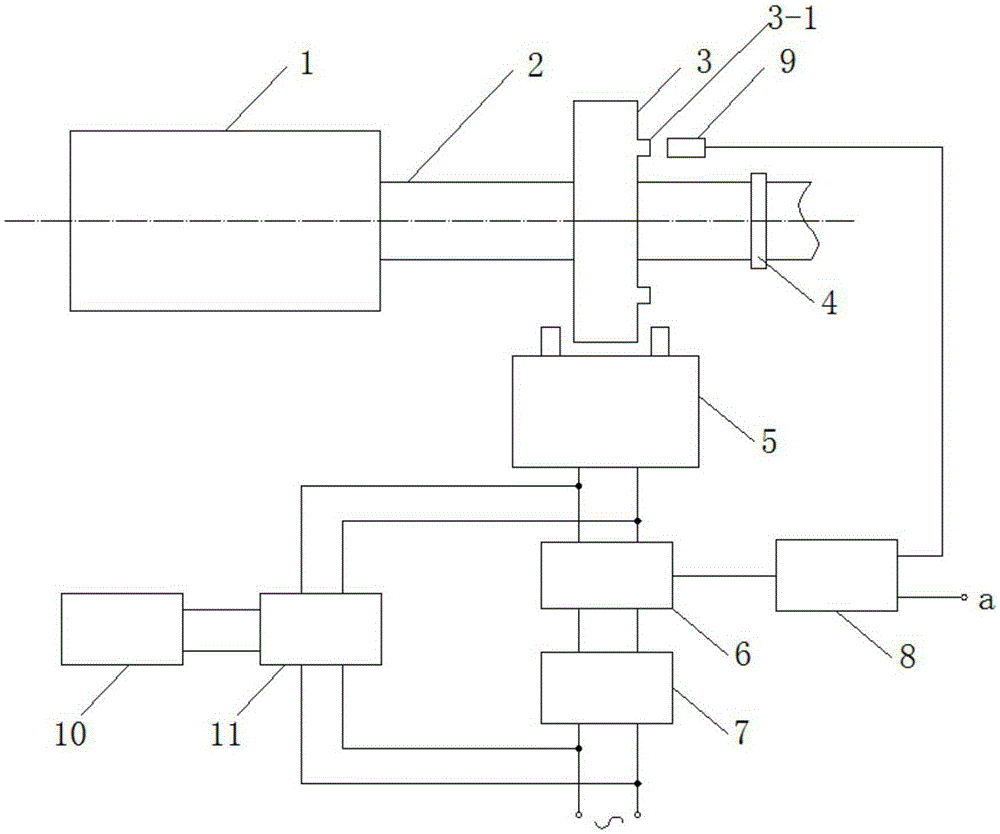
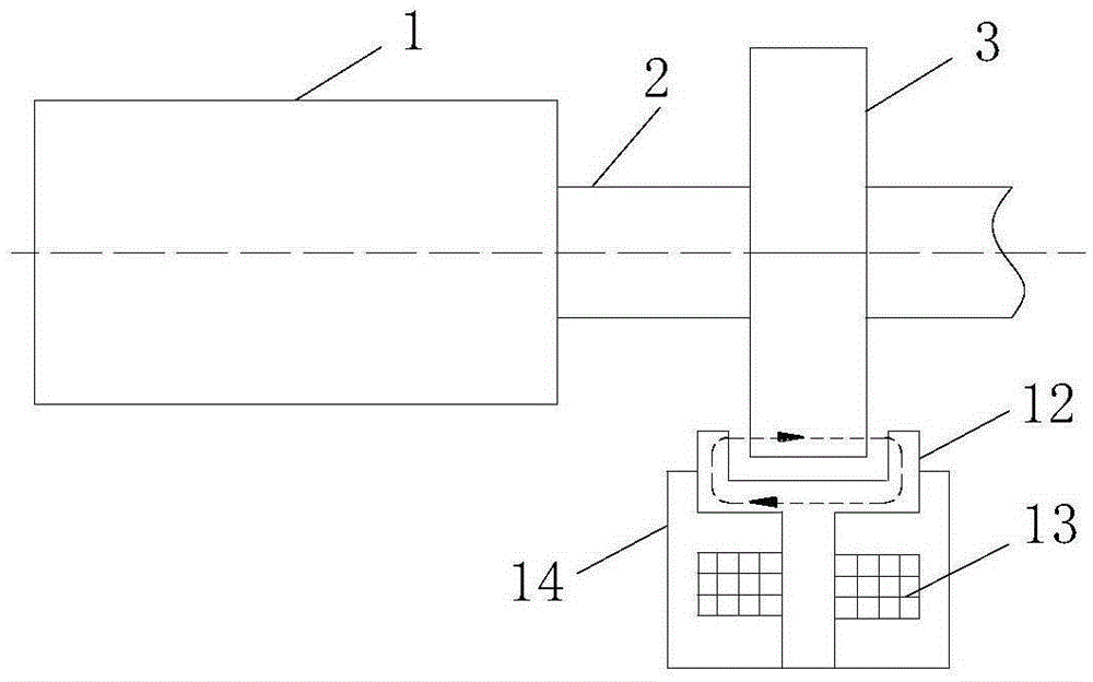
[0022] The rotating spindle electromagnetic brake device of the present invention has a structure such as figure 1 Shown, including braking part, excitation power supply and measurement and control part. The braking part includes a high-permeability electromagnetic brake disc 3 and a DC electromagnet 5 arranged on the main shaft 2. The main shaft 2 is also connected with a motor 1 and a coupling 4. The brake disc 3 is located at the two magnetic poles 12 of the DC electromagnet 5. Between them, they are not in contact with the DC electromagnet 5, and the positions of the shaft coupling 4 and the motor are respectively located on both sides of the brake disc 3. Two identical cylindrical magnet protruding blocks are arranged symmetrically on the right side of the brake disc 3 to detect the spindle speed. The size of the protruding blocks is de...


PUM


Abstract

The invention discloses an electromagnetic braking device for a rotary main shaft. The electromagnetic braking device comprises a braking part, an excitation power supply and a measurement and control part, wherein the braking part comprises a high-magnetic-conductive electromagnetic braking disc and a DC electromagnet which are arranged on the main shaft, the main shaft is further connected with a motor and a coupler, the braking disc is arranged between two magnetic poles of the DC electromagnet and is not in contact with the DC electromagnet, and the coupler and the motor are respectively arranged on both sides of the braking disc; and two identical cylindrical magnet protruding blocks are symmetrically arranged on the right side end surface of the braking disc. The electromagnetic braking device for rotary main shaft solves the problems that the traditional electromagnetic braking device has great electromagnetic loss, high temperature rise, cannot operate for a long time, cannot be applied to high-speed main shaft equipment and the like.

Description

technical field [0001] The invention belongs to the technical field of power control equipment, and in particular relates to an electromagnetic braking device for a rotating main shaft. Background technique [0002] Engines, motors, conveyors and other equipment powered by rotating spindles have been widely used in many industries such as equipment manufacturing, transportation, metallurgy and construction, and have become indispensable power equipment and braking devices in industrial production and life. It is a key link in the safe operation of power equipment, and improving the performance of the braking device is the basis for technological innovation and development of power equipment. [0003] Industrial brakes are mainly used in hoisting and transportation machinery, construction machinery, metallurgical and mining equipment, wind power and nuclear power equipment, ships and offshore heavy industry equipment. They are important power control devices in mechanical equ...

Claims


Application Information

Patent Timeline
IPC IPC(8): H02K49/02
Inventor 张小平邱荣华
Owner XI'AN POLYTECHNIC UNIVERSITY
Why Eureka
Try Eureka