Film forming device

A film forming device and film forming technology, which are applied in the directions of ion implantation plating, gaseous chemical plating, coating, etc., can solve the problems of complicated assembly operation, increased equipment cost, and difficult operation.

Inactive Publication Date: 2016-01-20
KOBE STEEL LTD
View PDF4 Cites 4 Cited by
  • Summary
  • Abstract
  • Description
  • Claims
  • Application Information

AI Technical Summary

Problems solved by technology

This complicates the assembly work of the entire device and makes maintenance difficult.
Specifically, when assembling the above-mentioned device, it is necessary to use a crane or the like to lift the heavy upper chamber and install the lower chamber below it in the state of lifting the heavy upper chamber, and to connect the above-mentioned upper chamber on the large-scale work. homework is not easy
In addition, when replacing and maintaining various parts in the upper chamber, the operator must enter the upper chamber from the upper side of the upper chamber at a higher position to perform operations. Sexual equipment costs also increase

Method used


Image

  • Film forming device
  • Film forming device
  • Film forming device

Examples


Embodiment Construction

[0015] Preferred embodiments of the present invention will be described with reference to the drawings.

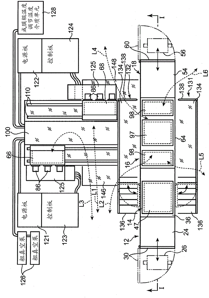
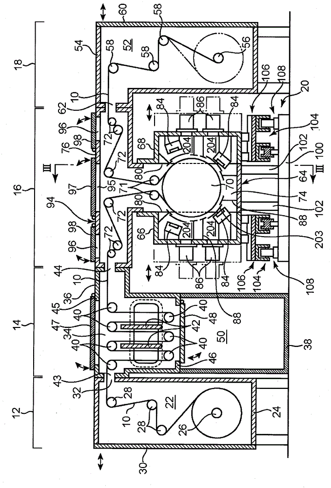
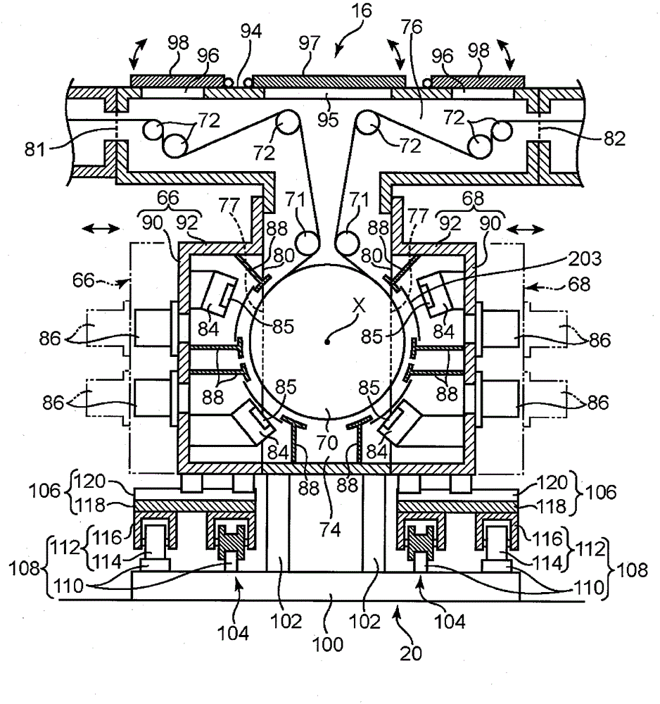
[0016] figure 1 The film forming apparatus shown is for forming a thin film on the surface of the film forming material 10 while conveying a long strip-shaped film forming material 10 made of, for example, a plastic film in its longitudinal direction. device. This film forming apparatus includes an unwinding unit 12 , a degassing unit 14 , a film forming unit 16 , and a winding unit 18 in the order of processing the above-mentioned film forming material 10 . The units 12 , 14 , 16 , and 18 are arranged sequentially along the horizontal direction, which is the transport direction of the film-forming material 10 . In this device, the horizontal direction (including the case of a slight inclination) perpendicular to the rotation center axis X of the film forming roller 70 described later corresponds to the left-right direction, and the direction parallel to the rotation cen...


PUM


Abstract

Provided is a film forming device which can secure work space without vertical overlap of the film forming unit and the units upstream and downstream thereof. This film forming device is provided with a film forming unit (16), and an upstream and downstream unit (14, 18) arranged to the left and right thereof. The film forming unit (16) is provided with: a film forming roller (70); multiple guide rollers (72); a main chamber (64) having a film forming roller housing unit (74) and, thereabove, a guide roller housing unit (76); a first and second process chamber (66, 68) which house multiple film forming process devices (84, 86) to the left and right of the film forming roller housing unit (74); and process chamber support units (104) for supporting the first and second process chamber (66, 68) so as to allow the first and second process chamber (66, 68) to move between a regular position for film formation and a retracted position retracted to the left or right, and between the retracted position and an exposure position separated in the front / back direction.

Description

technical field [0001] The present invention relates to a continuous film forming apparatus for forming a thin film such as a functional thin film on the surface of a strip-shaped film-forming material. Background technique [0002] Conventionally, as an apparatus for continuously film-forming a thin-walled film-forming material made of a long film or sheet, a structure is known in which the film-forming material is continuously conveyed in a vacuum chamber. , and various functional films are formed on its surface by sputtering or evaporation. [0003] As such a film forming apparatus, for example, Patent Document 1 discloses a structure including an upper chamber and a lower chamber. The lower chamber accommodates a film-forming roll capable of winding a film-forming material made of a film or the like, a plurality of sputtering sources for performing film-forming processing on the film-forming material, and the like. The lower chamber has left and right side walls on whi...

Claims


Application Information

Patent Timeline
Patent Type & Authority Applications(China)
IPC IPC(8): C23C14/56C23C16/54
CPCC23C14/562H01J37/32513H01J37/32733H01J37/3277H01J37/32807H01J37/3288H01J37/32899H01J37/3417H01L21/67132H01J37/3447H01J2237/162H01J2237/20278H01J2237/332
Inventor 濑川利规大庭尚树黑川好德
Owner KOBE STEEL LTD
Why Eureka
Try Eureka