Bending discharging device

A blanking and equipment technology, applied in the field of pipe bending, can solve the problems of complex operation, high maintenance cost, unreliable work, etc.

Inactive Publication Date: 2016-01-27
NINGBO T ERRE AUTOMOTIVE COMPONENTS
View PDF4 Cites 2 Cited by
  • Summary
  • Abstract
  • Description
  • Claims
  • Application Information

AI Technical Summary

Problems solved by technology

[0002] At present, the pipe benders on the market mainly include numerical control pipe benders, hydraulic pipe benders, etc., and the problems of high maintenance cost and complicated operation generally exist in the pipe benders of the prior art
In addition, the pipe bending machine in the prior art needs to put the pipe fittings into the pipe bending machine one by one, and take out the formed pipe fittings one by one after the pipe fittings are bent. It is easy to cause industrial injury to the operator who takes it out, that is to say, the pipe bender in the prior art also has safety problems due to the need to manually take the pipe.

Method used


Image

  • Bending discharging device
  • Bending discharging device
  • Bending discharging device

Examples


Embodiment Construction

[0016] The present invention will be further described below in conjunction with the accompanying drawings and specific embodiments.

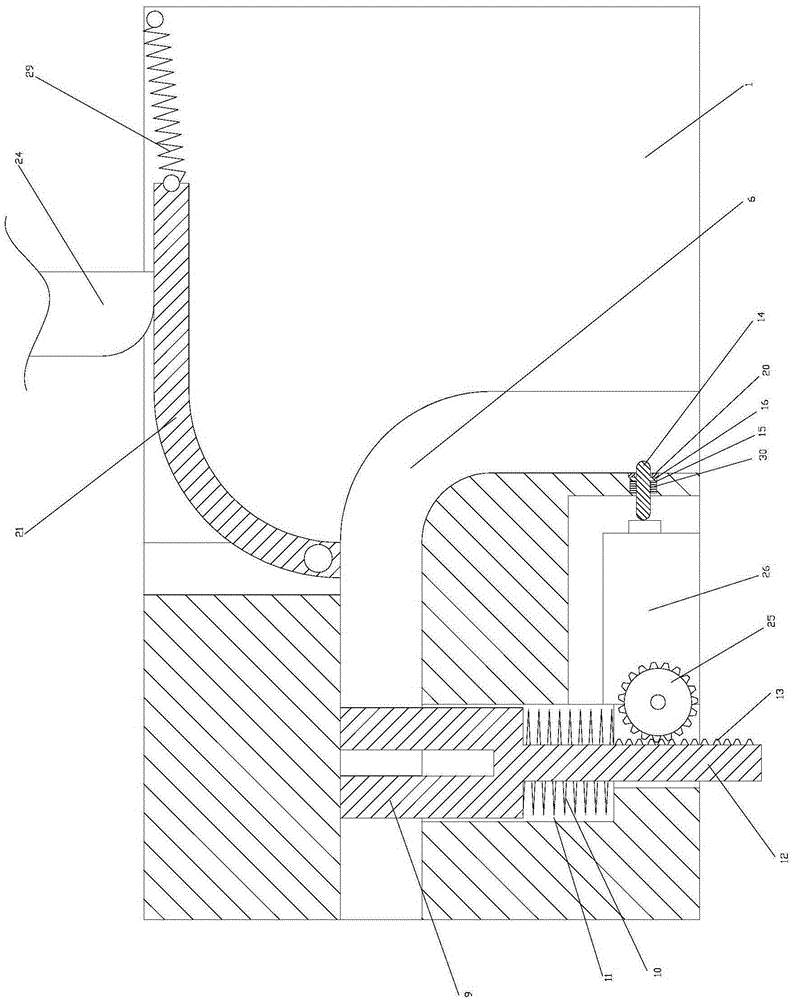
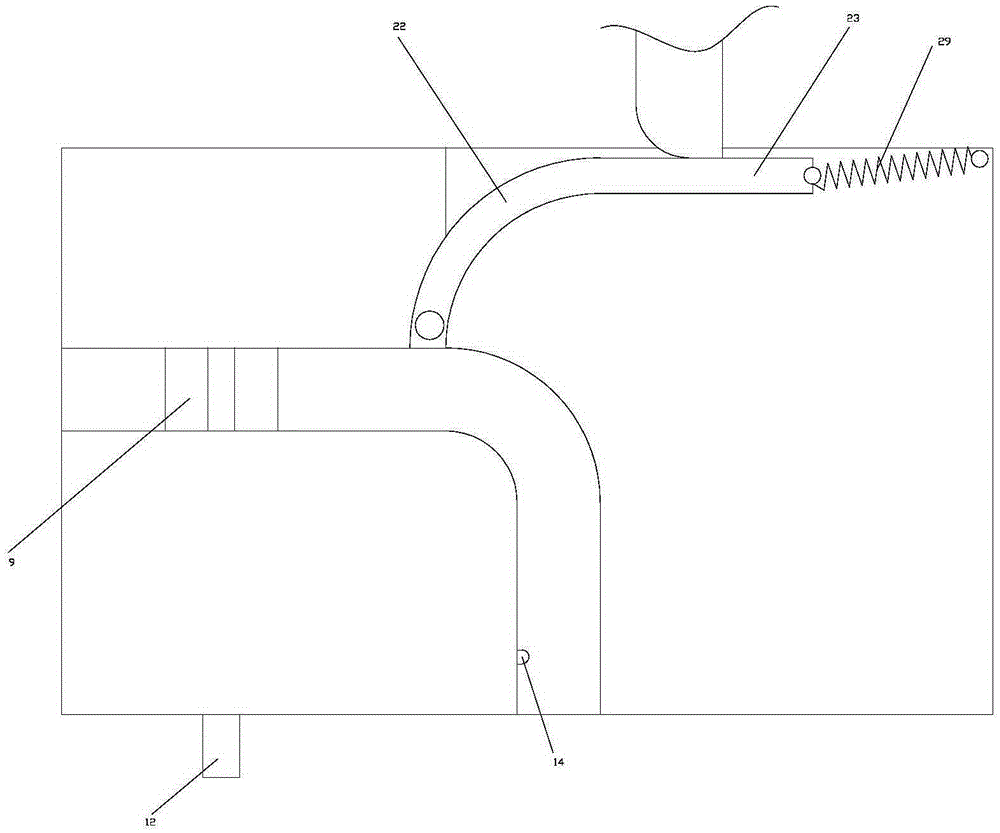
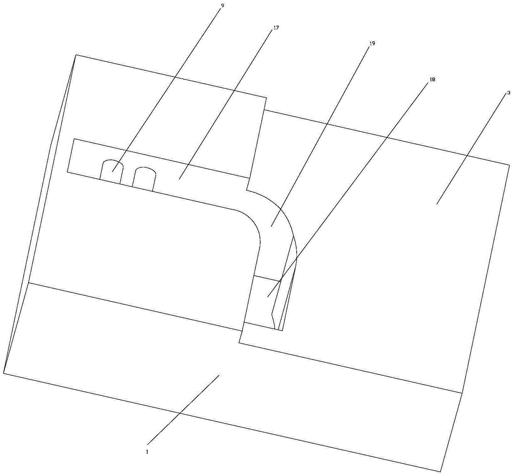
[0017] As shown in the figure, the working principle of the present invention: first, the cylindrical pin is displaced under the pressure of the first compression spring until the end of the cylindrical pin abuts against the inner wall of the first through hole; then one end of the unbent pipe is placed on the In the opening on the boss and above the cylindrical pin, the other end is placed horizontally on the reference surface on the base, such as Figure 4 shown;

[0018] Then, the punch on the hydraulic machine tool works to drive the rotating plate to rotate, so that the pipe is bent to conform to the shape of the through hole, such as Figure 5 As shown; during the rotation of the rotating plate, the third tension spring will also be pulled open, so that the third tension spring is deformed to reserve the force required for the reset of t...


PUM


Abstract

The invention discloses a bending discharging device. The bending discharging device comprises a base (1). The base (1) is provided with a reference face (3) used for carrying the free end of a pipe (2) and used for the free end of the pipe (2) to rotate. The base (1) is provided with a boss (4) higher than the reference face (3) so that the other end of the pipe (2) can be positioned. The boss (4) is provided with an opening (5) used for containing the end of the pipe (2). A through hole (6) for the bent pipe (2) to slide in the vertical direction is formed in the base (1) in the vertical direction, and the shape of the through hole (6) is consistent with the shape of the bent pipe (2). The bending discharging device is low in maintaining cost and easy and convenient to operate, and manual pipe taking is not needed.

Description

technical field [0001] The invention relates to the technical field of pipe bending, in particular to a bending and blanking equipment. Background technique [0002] At present, the pipe bending machines on the market mainly include numerical control pipe bending machines, hydraulic pipe bending machines, etc., but the problems of high maintenance cost and complicated operation generally exist in the pipe bending machines of the prior art. In addition, the pipe bending machine in the prior art needs to put the pipe fittings into the pipe bending machine one by one, and take out the formed pipe fittings one by one after the pipe fittings are bent. It is easy to cause industrial injury to the operator who takes it out, that is to say, the pipe bending machine in the prior art also has safety problems caused by the need to manually take the pipe. Contents of the invention [0003] The technical problem to be solved by the present invention is to overcome the existing technic...

Claims


Application Information

Patent Timeline
Patent Type & Authority Applications(China)
IPC IPC(8): B21D7/024B21D45/08
CPCB21D7/024B21D45/08
Inventor 陈荣发
Owner NINGBO T ERRE AUTOMOTIVE COMPONENTS
Why Eureka
Try Eureka