
Device for generating oil-containing water with micro air bubble

A technology for generating devices and micro-bubbles, which is applied in the directions of dissolution, liquid separation, chemical instruments and methods, etc., and can solve the problems of increasing the difficulty and limited treatment effect of the follow-up process of oil-water separation

Active Publication Date: 2010-06-09
浙江海牛海洋工程有限公司
View PDF2 Cites 4 Cited by
  • Summary
  • Abstract
  • Description
  • Claims
  • Application Information

AI Technical Summary

Problems solved by technology

[0008] Using the above-mentioned several methods, the air bubbles contained in the oily water obtained generally have a diameter of more than 20 microns, which is not delicate enough, which will relatively increase the processing difficulty of the subsequent process of oil-water separation. Emulsified and dissolved oils with very limited treatment effects

Method used


Image

  • Device for generating oil-containing water with micro air bubble
  • Device for generating oil-containing water with micro air bubble
  • Device for generating oil-containing water with micro air bubble

Examples


Embodiment 1

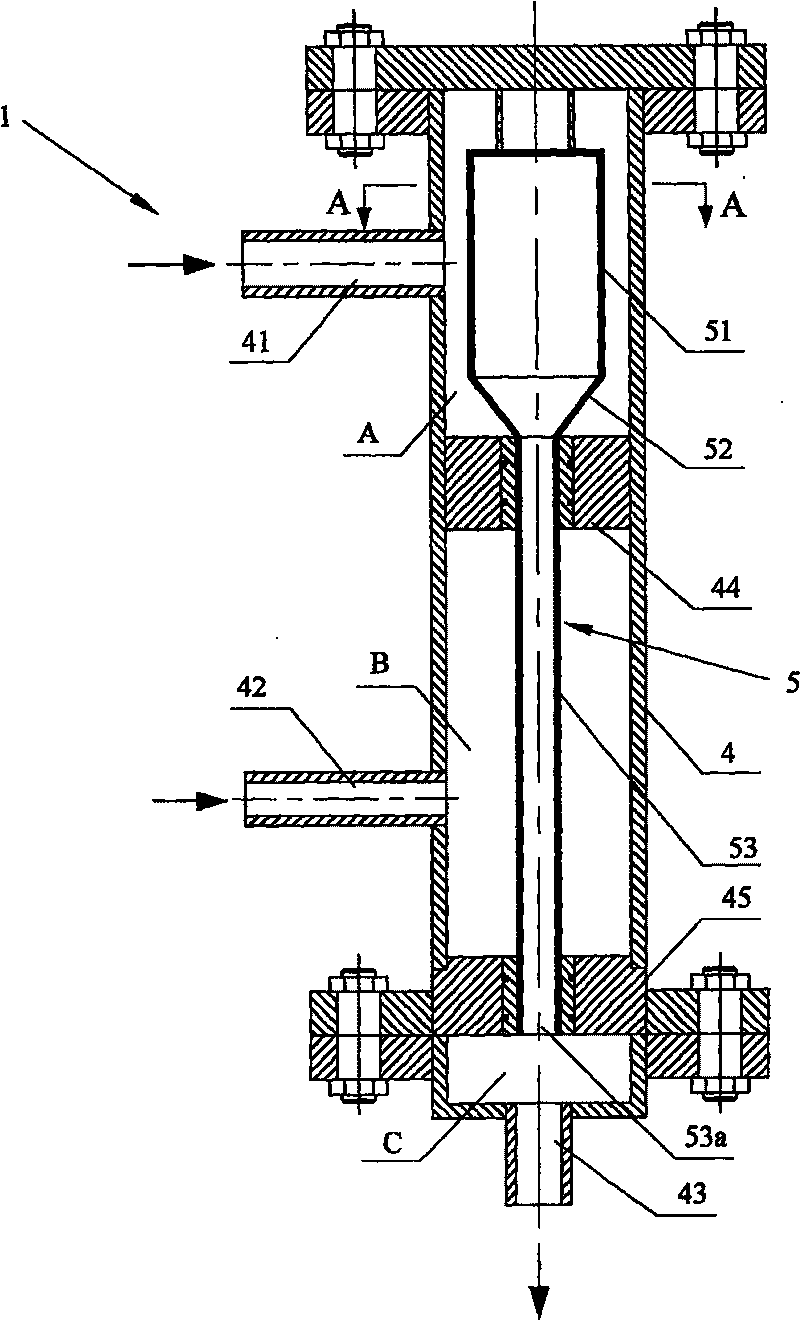
[0037] Such as Figure 1 to Figure 6 As shown, the generating device for oily water with fine bubbles is a combined device composed of a gas filter 2, a dissolved air water generator 1 and a large bubble remover 3 connected in sequence;

[0038] Among them, such as figure 1 Shown, described dissolved air water generator 1 comprises:

[0039] A top-sealed cylindrical container 4 has a water inlet 41 on its upper side wall, an air inlet 42 on the lower side wall, and a water outlet 43 on the bottom. The position between the gas ports 42 is provided with a first partition sealing plate 44, and the position below the air inlet 42 in the columnar container 4 is provided with a second partition sealing plate 45. The first and second partition sealing plates 44, 45 The inner cavity of the columnar container 4 is sequentially divided into a first liquid inlet chamber A, an air inlet chamber B, and a first liquid outlet chamber C from top to bottom;

[0040] A top-sealed swirl-type ...

Embodiment 2

[0053] Such as Figure 7 , Figure 8 , Figure 9 As shown, it is Embodiment 2 of the present invention. The difference between this Embodiment 2 and Embodiment 1 is: in the dissolved air water generator 1, how many are evenly distributed in the manner of central symmetry in the columnar container 4? A described swirl-type dissolved air water generating tube 5, in the described large bubble remover 3, a plurality of the swirl-type gas-liquid are evenly distributed in the columnar housing 6 in a center-symmetric manner Separation tube 7, its distribution mode can also refer to Figure 8 , to apply to the treatment of large flow oily water.


PUM


Abstract

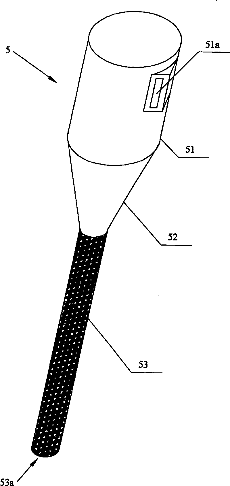
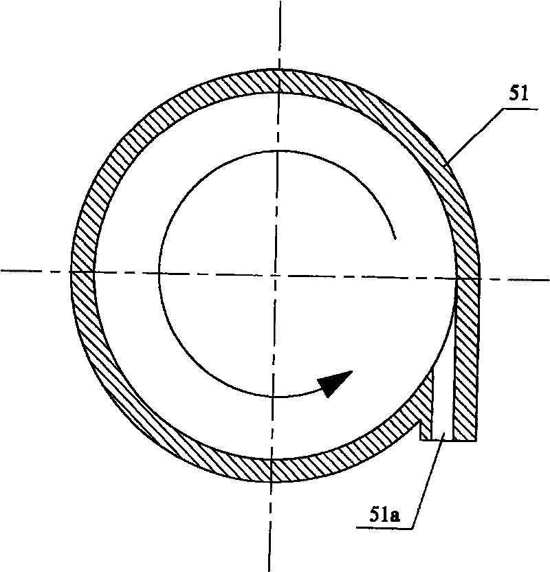
The invention discloses a generating device of oily water with micro bubbles, including an air-containing water generator (1); the air-containing water generator (1) consists of a columnar container (4) and a spiral-flow type air-containing water generation tub (5) in the columnar container, the place in the columnar container (4) which is positioned between a water inlet (41) and an air inlet (42) is provided with a first separation sealing plate (44), the place in the columnar container which is positioned below the air inlet (42) is provided with a second separation sealing plate (45), thespiral-flow type air-containing water generation tub (5) consists of a columnar sealed tube part (51), a conical sealed tube part (52) and a microporous tube part (53); wherein, the side wall of the columnar sealed tube part (51) is provided with a tangential diversion port (51a), an opening (53a) at the bottom of the microporous tube part (53) is communicated with a draining cavity (C) of the columnar container (4). Compared with the prior art, the bubbles in the oily water with micro bubbles generated by the device of the invention have smaller diameters and are subtler, therefore, the oil removal effect of following treatment technique can be more ideal.

Description

technical field [0001] The present invention relates to the technical field of oil-water separation treatment, in particular to a device for generating oily water with micro-bubbles used in the preliminary treatment stage of the oil-water separation process, which dissolves oily water into a large number of micro-bubbles for subsequent oil-water separation treatment prepare for. Background technique [0002] The oily water in the production process of oil and natural gas comes from various links such as oil and natural gas exploitation, processing, refining, storage and transportation. The water quality is complex, including crude oil, various impurities and chemicals added in the subsequent production and processing process and some microorganisms. [0003] Generally, the physical state of oil in oily water can be roughly divided into five types: slick oil, dispersed oil, emulsified oil, dissolved oil and solid-adhered oil. Usually, the above-mentioned physical states coex...

Claims


Application Information

Patent Timeline
Patent Type & Authority Patents(China)
IPC IPC(8): B01D17/035B01F3/04
Inventor 马立峰樊燕王守波
Owner 浙江海牛海洋工程有限公司
Learn More