
Assemble the inner magnet fixture of the keyboard aluminum rod

A technology for assembling jigs and inner magnets. It is used in manufacturing tools, metal processing, and metal processing equipment. It can solve problems such as high appearance defects, high overall misalignment, and defective scrap, and achieves a reduced misalignment rate and appearance. The effect of reducing the defective rate and the low defective scrap rate

Active Publication Date: 2017-10-13
QUNGUANG OPTOELECTRONICS SUZHOU
View PDF6 Cites 0 Cited by
  • Summary
  • Abstract
  • Description
  • Claims
  • Application Information

AI Technical Summary

Problems solved by technology

[0003] 1. Defective and scrapped high: due to the need to use quick-glue glue during assembly, when the length, width and height of a single magnet≦6.15*3.10*2.71mm, manual assembly is likely to cause the magnet to reverse, the position is incorrect, and the quick-glue glue After scrapping, the scrapping rate is 27%
[0004] 2. Low assembly efficiency: Assemble 20 magnets and 10 spacers in an aluminum rod groove with a length and width of 166.40*3.25mm, and each person assembles 20 pieces per hour
[0005] 3. Poor appearance: because there is quick glue in the groove of the aluminum rod, when the magnet is placed in the wrong position, it is easy to make the glue stick to the hand to correct it by hand. When the hand takes the aluminum rod, the aluminum rod product is also stuck to the glue , the defective rate is at 35%
[0006] 4. The overall misalignment is high: the magnets are manually assembled in the aluminum rod groove, because the total length of the aluminum rod groove is longer than the total length of 20 magnets and 10 spacers, the magnet needs to be centered in the groove, but manual assembly cannot be positioned Accurate, resulting in misalignment within 20%

Method used


Image

  • Assemble the inner magnet fixture of the keyboard aluminum rod
  • Assemble the inner magnet fixture of the keyboard aluminum rod
  • Assemble the inner magnet fixture of the keyboard aluminum rod

Examples


Embodiment Construction

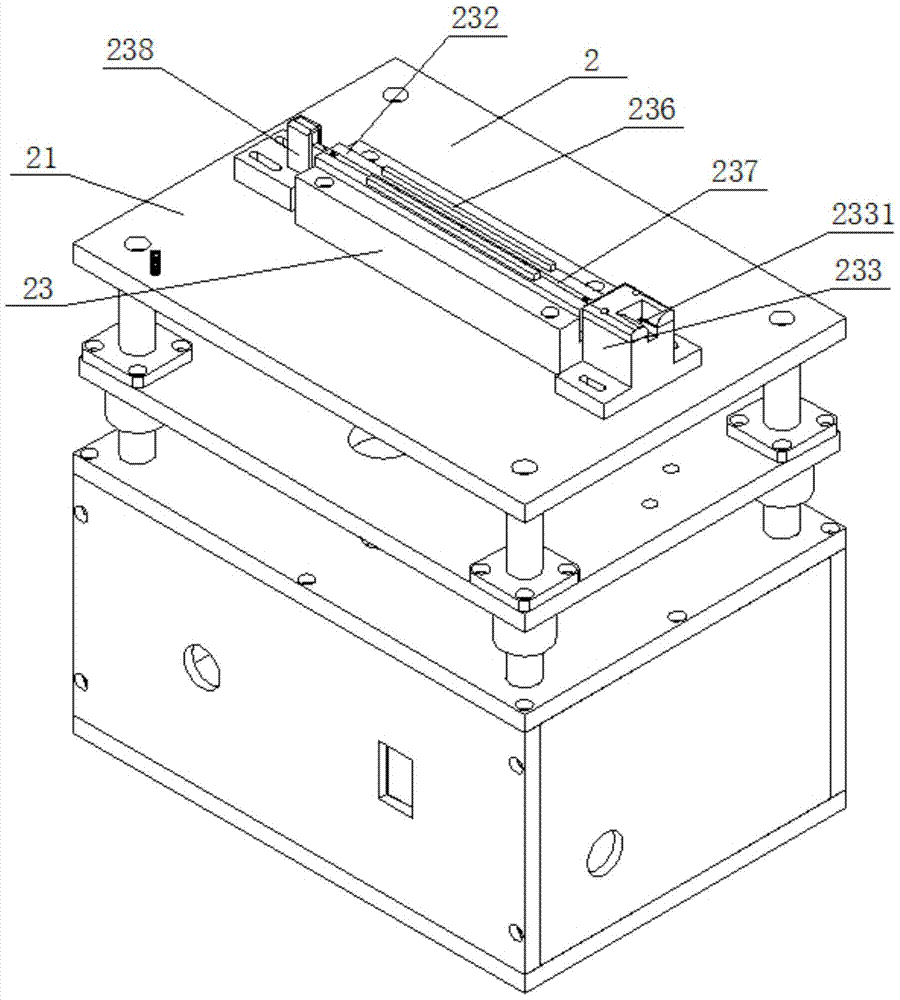
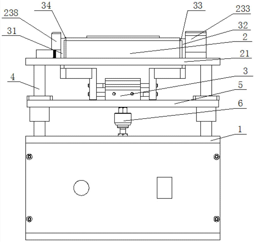
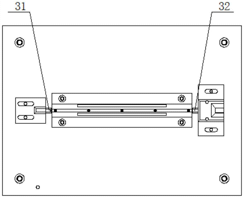
[0023] Such as Figure 1~4 The shown assembly keyboard aluminum bar inner magnet jig includes a machine platform 1, a magnet assembly jig 2 and parallel air claws 3, the magnet assembly jig 2 is arranged above the machine table 1, and the parallel air claws 3 It is arranged above the machine table 1 and below the magnet assembly jig 2 through a lifting mechanism.

[0024] The magnet assembly jig 2 includes a base 21 and a magnet positioning mechanism 23, the base 21 is supported on the top of the machine table 1 by at least two guide rods 4 and parallel to the table top, and the guide rods 4 are symmetrically arranged on the machine table 1 on both sides of the table top, the guide rod 4 is slidingly sleeved with a push plate 5, the push plate 5 is located between the table top of the machine table 1 and the base 21, the parallel air claw 3 is installed on the push plate 5, the machine A cylinder 6 for driving the push plate 5 to move up and down is installed on the platform ...


PUM


Abstract

The invention relates to a jig for assembling an inner magnet of an aluminum bar of a keyboard, including a machine table, a jig for assembling a magnet and parallel air claws. The jig for assembling a magnet includes a base and a magnet positioning mechanism. The magnet positioning mechanism includes three iron bars and two shaped stops The plate and the positioning block form two shaped intervals between the three iron bars, and the two shaped baffles are respectively arranged in the two shaped intervals, and a linear elastic body is arranged between the bottom surface of each strip baffle and the bottom surface of the bar shaped interval, The centered iron bar and the two baffles together form a strip-shaped groove. The positioning block is arranged at one end of the strip-shaped groove. The positioning block has a through hole corresponding to and connected with the strip-shaped groove. One end is provided with a stopper, and the left and right sliding claws of the parallel air claws respectively protrude from the base and are located at both ends of the bar-shaped groove, and the upper ends of the left and right sliding claws are all provided with protrusions. The invention provides an inner magnet jig for assembling keyboard aluminum rods with high assembly efficiency of bulk magnets, low defective scrap rate, low appearance defective rate and low overall deviation defective rate.

Description

technical field [0001] The invention relates to a jig for assembling an inner magnet of an aluminum bar of a keyboard, in particular to a jig for assembling a bulk magnet. Background technique [0002] At present, the assembly of multiple magnets in the aluminum rod slot of the keyboard is done manually. The following are the defects and deficiencies: [0003] 1. Defective and scrapped high: due to the need to use quick-glue glue during assembly, when the length, width and height of a single magnet≦6.15*3.10*2.71mm, manual assembly is likely to cause the magnet to reverse, the position is incorrect, and the quick-glue glue After scrapping, the scrap rate is 27%. [0004] 2. Low assembly efficiency: Assemble 20 magnets and 10 spacers in an aluminum rod groove with a length and width of 166.40*3.25mm, and each person assembles 20 pieces per hour. [0005] 3. Poor appearance: because there is quick glue in the groove of the aluminum rod, when the magnet is placed in the wrong...

Claims


Application Information

Patent Timeline
Patent Type & Authority Patents(China)
IPC IPC(8): B23P19/00
Inventor 高飞陈斌
Owner QUNGUANG OPTOELECTRONICS SUZHOU
Learn More