
An optical component storage and pick-and-place device

A pick-and-place device and technology for optical components, applied in packaging, internal accessories, transportation and packaging, etc., can solve the problems of optical component storage and pick-and-place pollution, and achieve accurate positioning, stable and reliable positions.

Active Publication Date: 2017-12-26
BEIJING GUOWANG OPTICAL TECH CO LTD
View PDF6 Cites 0 Cited by
  • Summary
  • Abstract
  • Description
  • Claims
  • Application Information

AI Technical Summary

Problems solved by technology

[0004] The purpose of the present invention is to propose a storage and pick-and-place device for optical components, which solves the problem of pollution in the storage and pick-and-place of optical components in the prior art, and realizes the two-way docking of storage and pick-and-place of optical components

Method used


Image

  • An optical component storage and pick-and-place device
  • An optical component storage and pick-and-place device
  • An optical component storage and pick-and-place device

Examples


Embodiment Construction

[0028] Embodiments of the present invention will be further described below in conjunction with the accompanying drawings.

[0029] An optical element storage and pick-and-place device of the present invention includes a storage device 1 and a clamping device 2;

[0030] See attached figure 1 , the storage device 1 includes a base 1-1, a boss 1-2, a radial locking nail A1-3 and a ball support 1-4; the three bosses 1-2 are evenly distributed on the circumference of the On the base 1-1, a radial locking nail A1-3 is arranged radially on the upper end of each boss 1-2, and the radial locking nails A1-3 arranged on the three bosses 1-2 are on the same On the plane, three ball supports 1-4 are evenly distributed on the circumference of the lower end surface of the base 1-1;

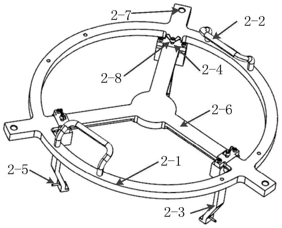
[0031] See attached figure 2 , the clamping device 2 includes a ring frame 2-1, a clamping hook 2-3, a position adjustment button 2-4, a slideway 2-6 and a thumb screw 2-8; the upper circumference of the r...


PUM


Abstract

The invention discloses an optical element storing, picking and placing device and belongs to the technical field of manufacturing and aligning of optical elements. The optical element storing, picking and placing device aims to solve the problem that in the prior art, optical elements are polluted when stored, picked and placed. The optical element storing, picking and placing device comprises a storing device and a clamping device. The storing device comprises a base, bosses, radial locking screws A and ball supports. The multiple bosses are evenly distributed on the circumference of the base. The radial locking screws A are arranged at the upper ends of the bosses in the radial direction respectively. The radial locking screws A arranged on the multiple bosses are located on the same plane. The m ball supports are evenly distributed on the circumference of the lower end face of the base. The clamping device comprises an annular frame, clamping hooks, position adjustment buckles, slideways and butterfly screws. The three slideways are evenly distributed on the circumference of the annular frame in the radial direction. The position adjustment buckles are arranged on the slideways. The lower end of each position adjustment buckle is fixedly connected with the corresponding clamping hook. The position adjustment buckles can slide on the slideways. The butterfly screws penetrate through the upper ends of the position adjustment buckles to make contact with the slideways. The butterfly screws are in threaded connection with the position adjustment buckles.

Description

technical field [0001] The invention belongs to the technical field of optical element manufacture and assembly, and in particular relates to an optical element storage and pick-and-place device. Background technique [0002] Optical components will be polluted by particles and molecular substances to varying degrees during manufacturing, storage and use. Contaminated optical components will inevitably suffer from performance degradation. Therefore, the cleaning guarantee of optical components is an important step in the development and production of optical instruments. problems that must be resolved. [0003] In the prior art, the pick-and-place process of optical components is directly operated by human hands touching the optical components. The most common type of pollution during the storage and pick-and-place process of optical components is dust, fingerprints, oil on the skin, etc. These pollutions are mainly caused by The reason is that when the storage carrier in c...

Claims


Application Information

Patent Timeline
Patent Type & Authority Patents(China)
IPC IPC(8): B65D61/00B65D25/10B65D85/38
Inventor 吴志会倪明阳王东平华洋洋李显凌隋永新杨怀江
Owner BEIJING GUOWANG OPTICAL TECH CO LTD
Learn More