
Evaporated fuel supply device

一种蒸发燃料、供给装置的技术,应用在燃料中加入非燃料物质、装料系统、发动机控制等方向,能够解决无法吸引吸附罐蒸发燃料等问题

Active Publication Date: 2018-07-17
AISAN IND CO LTD +1
View PDF9 Cites 0 Cited by
  • Summary
  • Abstract
  • Description
  • Claims
  • Application Information

AI Technical Summary

Problems solved by technology

However, when the pressure in the intake pipe is positive, the vaporized fuel in the canister cannot be sucked in, and even the intake air flows back from the intake pipe to the canister, so it is not ideal.

Method used


Image

  • Evaporated fuel supply device
  • Evaporated fuel supply device
  • Evaporated fuel supply device

Examples


Embodiment Construction

[0048] Hereinafter, the form for implementing this invention is demonstrated using drawing.

[0049] [Overall structure of the engine control system 1 including the evaporative fuel device ( figure 1 )]

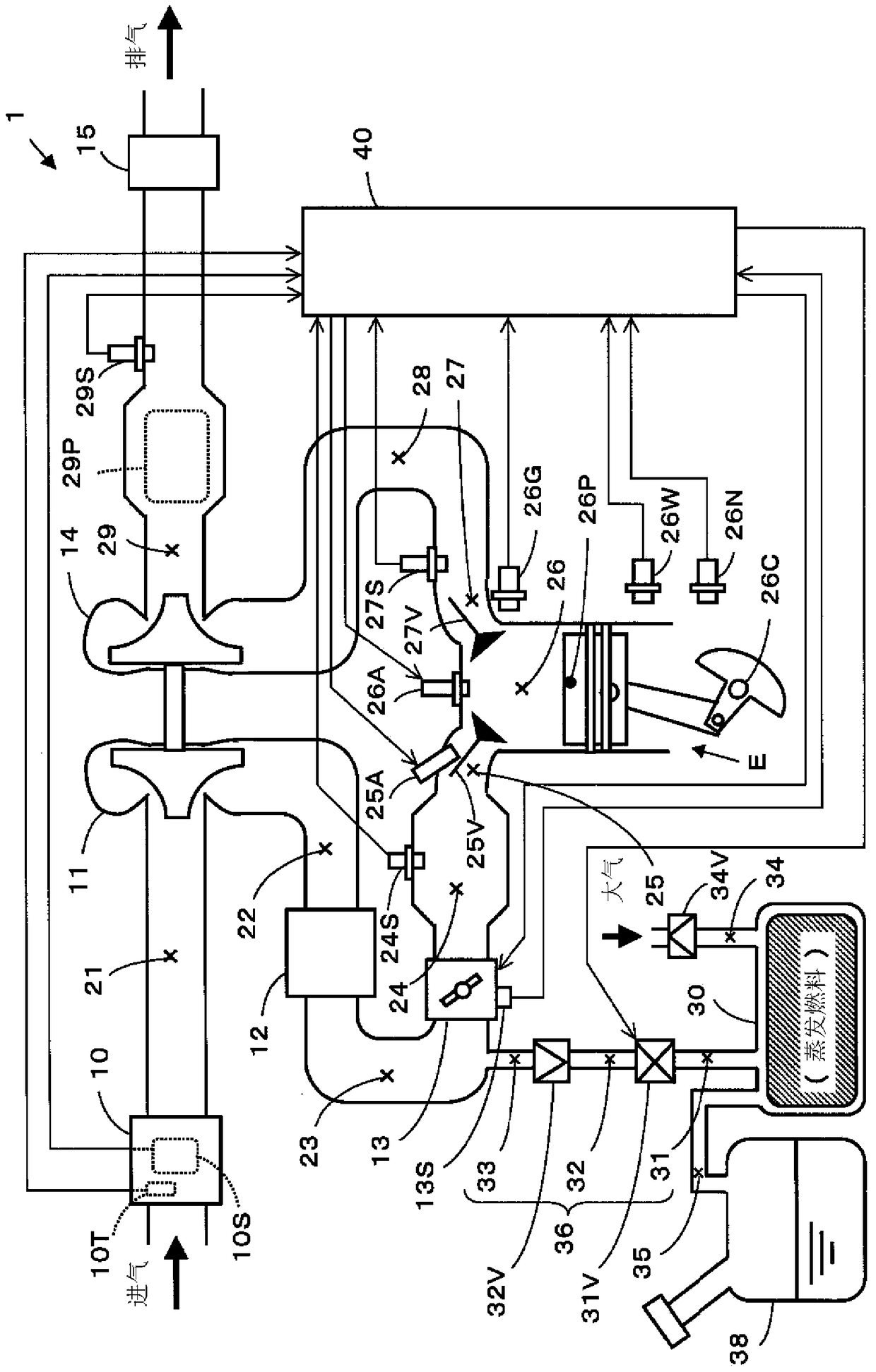
[0050] figure 1 An example of the overall configuration of the engine control system of a vehicle is shown. In addition, in the description of this embodiment, as an example of an internal combustion engine, a supercharger (in figure 1 In this example, a gasoline engine with a turbocharger) will be described as an example.

[0051] Such as figure 1 As shown, the engine control system 1 is controlled by the control unit 40, which is arranged in sequence from the intake side to the exhaust side with an air filter 10, an intake passage 21, a compressor 11, an intake passage 22, and an intercooler. 12. Intake passage 23, throttle valve 13, intake passage 24 (stabilizer box), intake manifold 25, combustion chamber 26, exhaust manifold 27, exhaust passage 28, turbine 14, e...


PUM


Abstract

The invention provides an evaporation fuel supply device. A purge valve is provided on the side of the adsorption tank in the purge passage, and a check valve is provided on the side of the intake passage, wherein, even if the part of the purge passage between the purge valve and the check valve remains under negative pressure In the case of the canister, the fluctuation of the air-fuel ratio can be further suppressed with a smaller number of parts in the purge control process of sucking the vaporized fuel in the canister to the internal combustion engine for combustion. A check valve (32V) and a purge valve (31V) that can be opened and closed by the control unit (40) are provided on the purge passage (36) connecting the adsorption tank (30) and the intake passage (23). The intake passage is equipped with a pressure detection unit, and the control unit can perform purge control for supplying evaporated fuel in the canister to the internal combustion engine by controlling the purge valve to an open state. The pressure and control state of the purge valve extrapolate the pressure in the intermediate purge passage.

Description

technical field [0001] The present invention relates to an evaporated fuel supply device for supplying evaporated fuel stored in a canister to an internal combustion engine through an intake pipe. Background technique [0002] Conventionally, for example, in a vehicle equipped with an internal combustion engine, evaporated fuel generated in a fuel tank or the like is temporarily stored (adsorbed) in a canister. Furthermore, during operation of the internal combustion engine (during operation satisfying a predetermined condition), purge control is performed to suck the evaporated fuel in the canister through the intake pipe while introducing atmospheric air into the canister. Attracted to the internal combustion engine causing it to burn. Furthermore, by performing this purge control, the evaporated fuel in the canister is combusted without being released into the atmosphere, thereby reducing the impact on the global environment. [0003] For example, in the case of a vehic...

Claims


Application Information

Patent Timeline
Patent Type & Authority Patents(China)
IPC IPC(8): F02M25/08
CPCF02D41/0032F02D41/0042F02D2041/1431F02D2200/0406F02M25/0836F02M25/089
Inventor 宫崎竜次堤英纪中塚智顺森广锦司本田光司
Owner AISAN IND CO LTD
Features
  • Generate Ideas
  • Intellectual Property
  • Life Sciences
  • Materials
  • Tech Scout
  • Unparalleled Data Quality
  • Higher Quality Content
  • 60% Fewer Hallucinations
Learn More