Oil injection pump

A technology of oil injection pump and pump body, which is applied in the direction of lubricating pumps, engine components, and engine lubrication, etc. It can solve the problems of low work efficiency, difficulty in filling, long filling time, etc., and achieve the effect of high work efficiency

Inactive Publication Date: 2016-01-27
HUBEI SHENYING LUBRICATION EQUIP
View PDF6 Cites 1 Cited by
  • Summary
  • Abstract
  • Description
  • Claims
  • Application Information

AI Technical Summary

Problems solved by technology

[0002] At present, the oil pumping unit in the oil field is lubricated with grease. During the repair or maintenance process of the pumping unit, the grease injection of the moving parts is generally manually operated with a grease gun. When adding butter to crank pins, maintenance workers have long used manual grease guns at high altitudes. First, the filling time is long and the work efficiency is low. Second, the viscosity of the butter is high and it is difficult to fill in winter. Workers work at heights for a long time, which is prone to safety accidents

Method used


Image

  • Oil injection pump
  • Oil injection pump
  • Oil injection pump

Examples


Embodiment Construction

[0016] In order to make the object, technical solution and advantages of the present invention clearer, the implementation manner of the present invention will be further described in detail below in conjunction with the accompanying drawings.

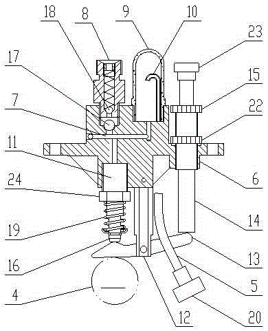
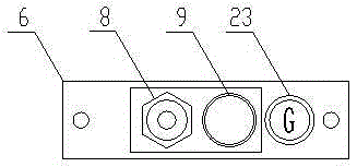
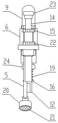
[0017] see Figure 1-3 , the embodiment of the present invention provides an oil injection pump, including a pump body 6, an oil passage 7 through which oil is supplied in the pump body 6, an oil outlet 8 on the upper part of the pump body 6, a vacuum cover 9 on the upper part of the pump body 6, and a vacuum cover The drip tube 10 in 9, the oil suction pipe 5 at the bottom of the pump body 6, the plunger cavity 11 vertically arranged at the bottom of the pump body 6, the pillar 12 at the middle position of the lower part of the pump body 6, the lever 13 hinged on the pillar 12, the pump body 6, the adjusting rod 14 that can be adjusted up and down and the adjusting nut 15 etc. that are located on the adjusting rod 14.

[0018] Among ...


PUM


Abstract

The invention discloses an oil injection pump and belongs to the technical field of mechanical lubricating. The oil injection pump comprises a pump body, an oil channel, an oil outlet, a vacuum hood, an oil dripping pipe, an oil suction pipe, a plunger cavity, a supporting column, a lever, an adjusting rod and an adjusting nut. The lower portion of the plunger cavity is provided with a plunger capable of sliding up and down. An oil storage chamber is arranged on the upper portion of the plunger cavity. The plunger cavity and the adjusting rod are arranged on the two sides of the supporting column respectively. The two ends of the upper side of the lever abut against the plunger and the adjusting rod respectively. The oil suction pipe is communicated with the oil dripping pipe through the oil channel and a first one-way valve is arranged on the oil suction pipe. The vacuum hood is communicated with the oil storage chamber through oil holes. The oil outlet is communicated with the oil storage chamber through the oil channel and a second one-way valve is arranged on the oil outlet. A spring capable of making the plunger reciprocate is arranged between the plunger and the pump body. The adjusting nut is arranged between the adjusting rod and the pump body. The oil injection pump can achieve automatic oil injection and is high in working efficiency, safe and reliable.

Description

technical field [0001] The invention relates to the technical field of mechanical lubrication, in particular to an oil injection pump. Background technique [0002] At present, the oil pumping unit in the oil field is lubricated with grease. During the repair or maintenance process of the pumping unit, the grease injection of the moving parts is generally manually operated with a grease gun. When adding butter to crank pins, maintenance workers have long used manual grease guns at high altitudes. First, the filling time is long and the work efficiency is low. Second, the viscosity of the butter is high and it is difficult to fill in winter. Workers work at heights for a long time, which is prone to safety accidents. Contents of the invention [0003] In order to solve the above problems, an embodiment of the present invention provides an oil injection pump, which can realize automatic oil injection. Described technical method is as follows: [0004] The embodiment of th...

Claims


Application Information

Patent Timeline
Patent Type & Authority Applications(China)
IPC IPC(8): F16N13/04
Inventor 方忠
Owner HUBEI SHENYING LUBRICATION EQUIP
Why Eureka
Try Eureka