Scram interlocking device and system

A technology of emergency stop interlock and emergency stop switch, applied in the direction of electrical program control, digital control, etc., to achieve the effect of simple structure, fast response of emergency stop interlock and less wiring

Active Publication Date: 2016-01-27
常州紫云英机电工程有限公司
View PDF6 Cites 8 Cited by
  • Summary
  • Abstract
  • Description
  • Claims
  • Application Information

AI Technical Summary

Problems solved by technology

[0003] The purpose of the present invention is to provide an emergency stop interlocking device to solve the problem that the emergency stop of the entire line cannot be realized by the emergency stop switch on any piece of equipment on the assembly line.

Method used


Image

  • Scram interlocking device and system
  • Scram interlocking device and system

Examples


Embodiment 1

[0014] The following specifically introduces an emergency stop interlock system for CNC machine tools.

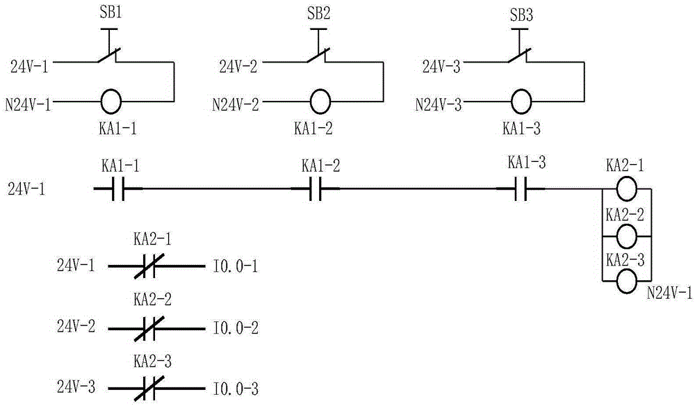
[0015] Such as figure 1 As shown, for the three CNC machine tools and the corresponding emergency stop interlock devices, the emergency stop interlock devices include: each machine tool is equipped with an emergency stop signal generation circuit, that is, the emergency stop signal generation circuit of the first CNC machine tool is controlled by the emergency stop signal generation circuit. The stop switch SB1 and the detection relay coil KA1-1 are formed in series, the emergency stop signal generating circuit of the second CNC machine tool is formed by the emergency stop switch SB2 and the detection relay coil KA1-2 in series, the emergency stop signal input circuit of the third CNC machine tool The emergency stop switch SB1 and the detection relay KA1-3 are connected in series, and the power supply for the three emergency stop signal generating circuits is 24V. Three co...

Embodiment 2

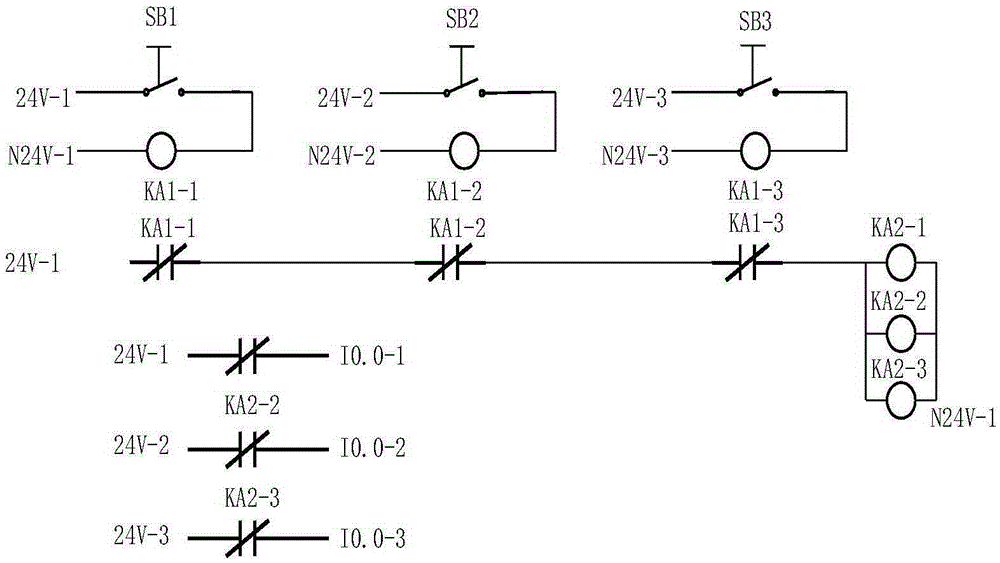
[0018] Above-mentioned embodiment 1 has provided the embodiment that the emergency stop switch is a normally closed switch, and the contact of the detection relay is a normally open contact. As other embodiments, the emergency stop switch can also be a normally open switch, and the contact of the detection relay is Normally closed contacts, such as figure 2 As shown, the only difference from Embodiment 1 is that the emergency stop switch is a normally open switch, and the contacts of the detection relays KA1-1, KA1-2 and KA1-3 are normally closed contacts.

[0019] When the assembly line is working normally, each CNC machine tool is running normally. At this time, the emergency stop switch is in the disconnected state, the detection relays KA1-1, KA1-2, and KA1-3 are in the power-off state, and the control relays KA2-1, KA2-2 , KA2-3 is in the energized state, the normally closed contacts of the detection relays KA1-1, KA1-2, KA1-3 are closed, and the normally closed contacts...


PUM


Abstract

The invention relates to a scram interlocking device and system, and the system comprises numerically-controlled machine tools, N detection relays which are used for detecting scram signals, and N control relays which are used for controlling the scram signals to be inputted into a control, wherein N is greater than one. Each numerically-controlled machine tool is provided with a scram signal generation loop which is formed by the series connection of a scram switch and a detection relay coil. The corresponding contacts of N detection relays and N control relay coils in parallel connection are in series connection to form an interlocking control loop. One contact of each control relay is used for connecting a scram signal input terminal of the corresponding numerically-controlled machine tool. The device is simple in structure and is smaller in number of wires. The control power supplies of all equipment are isolated, and the scram signal of any one piece of equipment can be quickly fed back to other background equipment. The device is high in scram interlocking response speed, can effectively solve a problem that a production line cannot achieve full-line scram through the scram switch of any one piece of equipment.

Description

technical field [0001] The invention relates to an emergency stop interlock device and system, in particular to an emergency stop interlock device and system for multiple numerical control machine tools. Background technique [0002] With the development of industrial modernization, automation, and intelligence, and the continuous advancement of Industry 4.0, the large-scale assembly line processing operations in enterprises have become more and more intelligent and automated. Using truss robots to connect multiple CNC machine tools into an unmanned Operation of automated production lines has become a trend. However, on the automated production line, the emergency stop switch is set on each single CNC machine tool. Pressing an emergency stop switch can only emergency stop one CNC machine tool, and other CNC machine tools are still in working condition, which makes the emergency stop machine in front of the machine tool The backlog of products and the cut-off of products aft...

Claims


Application Information

Patent Timeline
Patent Type & Authority Applications(China)
IPC IPC(8): G05B19/19
CPCG05B19/19
Inventor 苏建新李聚波聂少武徐严冬张艳珍刘明鸣王建生王全胜
Owner 常州紫云英机电工程有限公司
Why Eureka
Try Eureka