Current source for voltage regulator and its voltage regulator

A technology of current source and voltage regulator, which is applied in the field of current source and its voltage regulator, and can solve problems such as the reduction of voltage stabilization effect

Active Publication Date: 2017-03-01
NOVATEK MICROELECTRONICS CORP
View PDF2 Cites 0 Cited by
  • Summary
  • Abstract
  • Description
  • Claims
  • Application Information

AI Technical Summary

Problems solved by technology

Even for a voltage regulator that includes a voltage stabilizing capacitor, its voltage stabilizing effect is more likely to be affected by the parasitic impedance of the chip's external or internal circuits as the load current demand increases.

Method used


Image

  • Current source for voltage regulator and its voltage regulator
  • Current source for voltage regulator and its voltage regulator
  • Current source for voltage regulator and its voltage regulator

Examples


Embodiment Construction

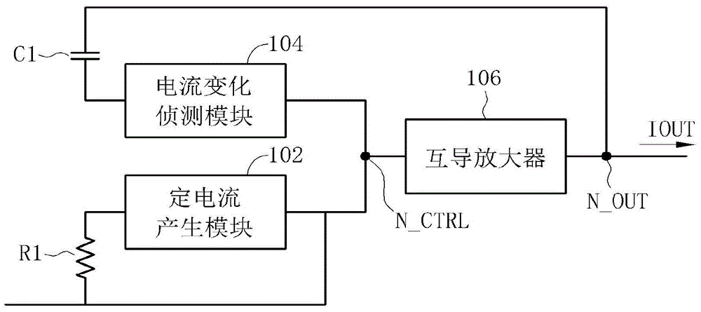
[0043] Please refer to figure 1 , figure 1 It is a schematic diagram of a current source 10 according to an embodiment of the present invention. Such as figure 1 As shown, the current source 10 includes a certain current generating module 102 , a capacitor C1 , a current change detecting module 104 and a transconductance amplifier 106 . The constant current generating module 102 is coupled to a control node N_CTRL for generating a rated current to flow through the control node N_CTRL to determine the voltage of the control node N_CTRL. The main purpose of the rated current is to adjust the bias voltage of the control node N_CTRL. In the case of avoiding excessive power consumption, the rated current can be set to a smaller current. The capacitor C1 is coupled between an output terminal N_OUT of the current source 10 and the current variation detection module 104 . The current change detection module 104 is coupled between the control node N_CTRL and the capacitor C1, which...


PUM


Abstract

The invention discloses a current source and voltage stabilizers. The current source is used for rapidly adjusting output current and comprises a current generating module, a capacitor coupled to an output end of the current source, a current-varying detection module and a transconductance amplifier. The current generating module is coupled to one control node, which is used for generating rated current passing through the control node for the purpose of controlling voltage at the control node. The current-varying detection module is coupled between the control node and the capacitor so that voltage at the control node varies via the capacitor when the output end of the current source receives variation in instantaneous current. The transconductance amplifier is coupled between the control node and the output end so that magnitude of output current at the output end is correspondingly varied when voltage at the control node varies.

Description

technical field [0001] The invention relates to a current source for a voltage stabilizer and a voltage stabilizer thereof, in particular to a current source capable of quickly adjusting the output current of a voltage stabilizer and a voltage stabilizer thereof. Background technique [0002] A voltage regulator (voltage regulator) usually uses a feedback circuit to lock the output voltage it intends to generate, and a voltage stabilizing capacitor is provided at the output end of the voltage regulator to assist the voltage stabilizing capability of the voltage regulator. Among them, the setting of the voltage stabilizing capacitor is mainly to convert the pre-stored charge into the driving current and supply it to the load when the demand current of the load driven by the voltage regulator changes rapidly, so as to maintain the output voltage of the output terminal of the voltage regulator. of stability. In other words, if the voltage regulator is to withstand a large chan...

Claims


Application Information

Patent Timeline
Patent Type & Authority Patents(China)
IPC IPC(8): G05F1/56
Inventor 胡敏弘黄秋皇吴振聪黄俊为苏品翰
Owner NOVATEK MICROELECTRONICS CORP
Why Eureka
Try Eureka