Integrated small reactor

A reactor, a small-scale technology, applied in the direction of reactors, greenhouse gas reduction, nuclear power generation, etc., can solve problems such as damaged bullets, limited space for safety performance improvement, hidden dangers of reactor safety, etc., to ensure structural stability and reliability, and eliminate major damage Mouth accidents, fixed safety improvement effect

Active Publication Date: 2016-01-27
NUCLEAR POWER INSTITUTE OF CHINA
View PDF5 Cites 15 Cited by
  • Summary
  • Abstract
  • Description
  • Claims
  • Application Information

AI Technical Summary

Problems solved by technology

[0002] Most of the common pressurized water reactors are arranged in a scattered manner. The steam generator and the pressurizer are placed in an independent space outside the reactor pressure vessel, and the main pump is placed on the main pipeline. They are all at a certain distance from the reactor pressure vessel. The space is relatively large; the control rod driving mechanism is located on the top cover of the pressure vessel, and the external structures such as ventilation, supporting wires, and anti-seismic structures are large in size and heavy in weight.
In addition, since the main pipe and the control rod driving mechanism are the pressure boundary, there is a possibility of damage and rod ejection accidents, which bring safety hazards to the reactor
The reactor generally has a large power, poor layout flexibility, limited space for safety performance improvement, and cannot meet people's diverse needs for power supply, heating, steam supply, refrigeration, oil extraction, etc.

Method used


Image

  • Integrated small reactor
  • Integrated small reactor
  • Integrated small reactor

Examples


Embodiment Construction

[0025] The present invention will be described in further detail below in conjunction with the accompanying drawings and specific embodiments.

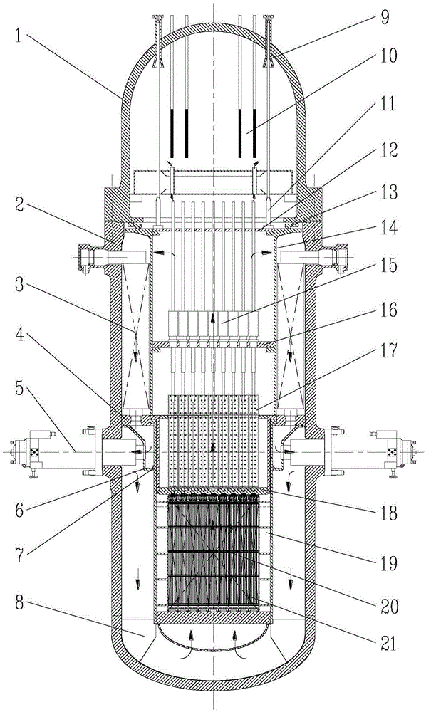
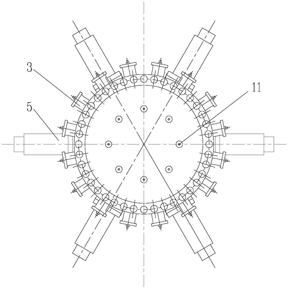
[0026] Such as figure 1 and figure 2 As shown, the integrated small reactor has a built-in pressure stabilizing device consisting of a steam generator, a control rod drive mechanism and a heating tube.

[0027] The annular supporting platform 4 is welded in the pressure vessel cylinder 2, and the core hanging basket 19 and the flange of the pressing assembly 18 are suspended thereon through such a structure. The fuel assembly 20 is placed in the core basket 19 and is compacted by the compaction assembly 18 . The top of the compression assembly 18 is the compression cylinder 14 and the compression spring 13 in turn, and the axial load generated by the pressure vessel top cover 1 compressing the compression spring 13 will eventually compress the compression cylinder 14, the core basket 19, the fuel assembly 20 and the The compressio...


PUM


Abstract

The invention belongs to the pressurized water reactor overall structure design technology, and specifically discloses an integrated small reactor. The integrated small reactor comprises a pressure vessel, and a reactor core, a compressing assembly, a control rod assembly, a guide assembly, a control rod driving mechanism and a once-through steam generator which are arranged inside the pressure vessel, and further comprises a main pump directly connected with a cylindrical body of the pressure vessel, wherein the reactor core comprises a reactor core barrel and a fuel assembly; the compressing assembly and the control rod assembly are arranged inside the reactor core barrel; and the pressure vessel is directly connected with the main pump, the main pump is horizontally installed, and an inlet thereof is provided with a flow distribution device. Heating equipment is arranged on a top cover of the pressure vessel, a coolant inside the pressure vessel is subjected to pressure control directly through temperature adjustment, that is, main equipment such as the steam generator, voltage-stabilizing equipment and the control rod driving mechanism are arranged inside the pressure vessel of the reactor at the same time. According to the integrated small reactor, the external loop pipeline is omitted, large break accidents are eliminated, and the structure is compact; and the control rod driving mechanism is arranged internally, the rod ejection accident is eliminated, and the fixation safety is greatly improved.

Description

technical field [0001] The invention belongs to the overall structure design technology of a pressurized water reactor, and in particular relates to an integrated small reactor with a built-in steam generator, a control rod driving mechanism and a voltage stabilizer. Background technique [0002] Most of the common pressurized water reactors are arranged in a scattered manner. The steam generator and the pressurizer are placed in an independent space outside the reactor pressure vessel, and the main pump is placed on the main pipeline. They are all at a certain distance from the reactor pressure vessel. The space is relatively large; the control rod driving mechanism is located on the top cover of the pressure vessel, and ventilation, wire support, and anti-seismic structures are arranged on the outside, which is bulky and heavy. In addition, since the main pipe and the control rod driving mechanism are pressure boundaries, there is a possibility of damage and rod ejection a...

Claims


Application Information

Patent Timeline
Patent Type & Authority Applications(China)
IPC IPC(8): G21D1/02G21D1/04G21C13/02
CPCY02E30/00Y02E30/30
Inventor 陈训刚许斌罗英张宏亮王留兵饶琦琦赵伟杨敏杨晓晨李浩颜达鹏
Owner NUCLEAR POWER INSTITUTE OF CHINA
Why Eureka
Try Eureka