Motor stator

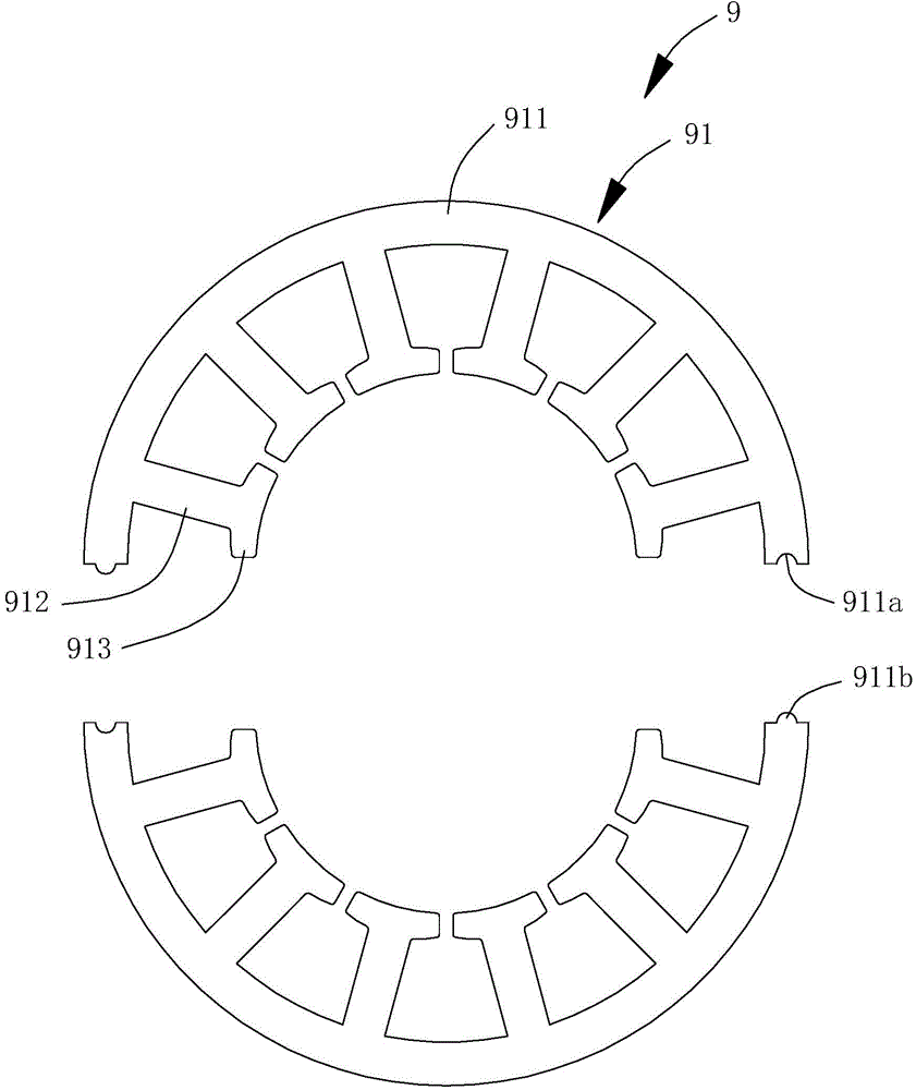
A motor stator and stator block technology, applied in the direction of magnetic circuit static parts, magnetic circuit shape/style/structure, etc., can solve the problems of complex processing and assembly, complex winding processing and assembly steps of stator block 91, and lengthy production time, etc.

Active Publication Date: 2016-01-27
SUNONWEALTH ELECTRIC MACHINE IND
View PDF6 Cites 3 Cited by
  • Summary
  • Abstract
  • Description
  • Claims
  • Application Information

AI Technical Summary

Problems solved by technology

However, taking a part of the "12-slot" three-phase motor as an example, every two adjacent magnetic poles of the stator need to be wound with coils of the same phase. Since the stator block 91 includes six magnetic poles, the support portion of the single stator block 91 912 needs to wind coils of three different phases at the same time, and when the two stator blocks 91 are assembled with each other, the coils of the three different phases on the two stator blocks 91 must be electrically connected to each other in pairs, resulting in the The winding processing and assembly steps of the stator block 91 are complicated, which makes the overall manufacturing of the motor stator too difficult
[0006] To sum up, the silicon steel sheet 81 of the existing stator assembly structure 8 forms a single magnetic pole, resulting in a time-consuming process of making a motor stator using the silicon steel sheet 81; relatively, although the arc-shaped yoke 911 of the existing motor stator 9 can be extended Several support parts 912 are provided to form several magnetic poles, but the support part 912 of a single stator block 91 needs to be wound with several coils of different phases at the same time, which makes the winding process and assembly steps of the stator block 91 complicated.
In view of this, there is an urgent need to provide a further improved motor stator to solve the problems of long production time or complicated processing and assembly of the existing combined motor stator.

Method used


Image

  • Motor stator
  • Motor stator
  • Motor stator

Examples


Embodiment Construction

[0063] In order to make the above-mentioned and other purposes, features and advantages of the present invention more obvious and understandable, the preferred embodiments of the present invention are specifically cited below, together with the accompanying drawings, as follows:

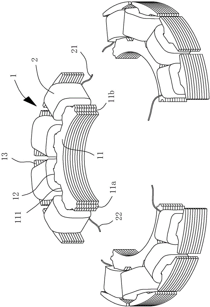
[0064] Please refer to image 3 and Figure 4 Shown is the motor stator of the first embodiment of the present invention, the motor stator includes several stator blocks 1, each of which is wound with a coil 2, and the several stator blocks 1 can be assembled and combined with each other. Each stator block 1 includes a yoke portion 11 and several poles 12. Specifically, for any stator block 1, the stator block 1 includes a single yoke portion 11, and the several poles 12 are respectively connected to The yoke part 11 is connected with a pole piece 13 at the end of each pole post 12 away from the yoke part 11 . The yoke portion 11 preferably has an arc surface 111, and the plurality of pole columns 12...


PUM


Abstract

A motor stator is disclosed for reducing processing and assembling complexity of a combined type motor stator. The motor stator includes a plurality of stator blocks. Each stator block includes a magnet yoke, wherein the magnet yoke connects a plurality of poles, and an end of each pole away from the magnet yoke is connected with a pole shoe. A wire is wound onto the plurality of poles of each stator block to form a coil with single phase. Two ends of the coil are provided with a first electric contact and a second electric contact respectively.

Description

technical field [0001] The invention relates to a motor stator, in particular to a combined motor stator formed by assembling several stator blocks. Background technique [0002] Please refer to figure 1 As shown, it is an existing stator assembly structure 8. The stator assembly structure 8 includes a roughly arc-shaped and I-shaped silicon steel sheet 81. One side of the silicon steel sheet 81 is provided with a pointed point protruding outward. The other side of the inclined rib 811 is provided with a pointed and oblique groove 812 corresponding to the rib 811, so that when several silicon steel sheets 81 are assembled, the rib 811 of the previous silicon steel sheet 81 can be engaged. The buckle groove 812 of the next silicon steel sheet 81 forms a tight positioning. An embodiment of the conventional stator assembly structure 8 has been disclosed in Taiwan Patent Publication No. M277182 "Improvement of Silicon Steel Sheet Assembly Structure". [0003] However, the abo...

Claims


Application Information

Patent Timeline
IPC IPC(8): H02K1/12
Inventor 伊佐国单多年邱柏伟
Owner SUNONWEALTH ELECTRIC MACHINE IND
Why Eureka
Try Eureka