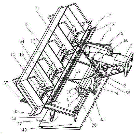
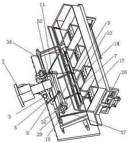
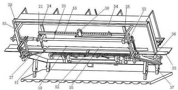
[0032] Such as Figure 1~Figure 7 A rice transplanter shown includes a frame 1, a power input box 2 is provided on the frame 1, and the power input box 2 is connected to a rotating shaft 3 in a chain drive. A rod A4, a rocker B5, the rocker A4 is connected to one side of the seedling pawl frame 7 through a connecting rod E6, and the rocker B5 is connected to the vertical rod 9 on the seedling pawl frame 7 through a connecting rod F8. Bearing seats 10 are installed at both ends. The bearing seats 10 are fixed on the drive shaft B11 on the frame 1, and the seedling claw frame 7 is provided with a seedling claw 12, and the rotating shaft 3 drives the seedling claw 11 from The seedling box 13 is grabbed and inserted into the soil. The seedling box 13 reciprocates along the track 33 on the frame 1. The track 33 is provided with a seedling opening 34, and the seedling box 13 is provided with a reciprocating movement. The seedling box 13 is provided with a layer of seedling blocking plates 15 at the upper and lower parts of the seedling box 13 respectively. The open side of the seedling box 13 is provided with a seedling rack 16 which is A seedling limiting block 17 is provided on the lower frame of the seedling support frame 16, and a seedling support auxiliary frame 18 extends outside the lower frame of the seedling collecting frame 16. The back of the seedling plate 14 is provided with a connecting post. The connecting post passes through the opening 19 on the back plate of the seedling box 13 and is connected to the slat 20. The two sides of the slat 20 pass through the linkage mechanism G21 and the linkage mechanism H22. Connected to the rotating shaft 23, the rotating shaft 23 passes through the support block 25 provided on the cross beam 24, and one end is rotatably connected to the support plate 26 on the seedling box 13. A section of the rotating shaft 23 is rectangular in cross section, and the rectangular section Pass through the rectangular hole on the connecting piece 28 at the input end of the link mechanism D27. The input end of the link mechanism D27 is connected to one end of the drive shaft D29, and the drive shaft D29 and the drive shaft B11 are connected through a link mechanism C30. One side edge of the seedling block 15 is connected to the back plate of the seedling box obliquely downward, and the included angle with the back plate of the seedling box is 10-30 degrees. The two ends of the edge respectively touch the partitions 31 in the seedling box 13. The inclination angle of the seedling plate 14 is consistent with the inclination angle of the seedling blocking plate 15. The downwardly inclined lower edges of the seedling blocking plate 15 and the seedling pulling sheet 14 are saw-toothed. The U-shaped sides of the lower frame of the seedling frame 16 are provided with several bolt holes, the U-shaped claw end of the seedling sub-frame 18 is provided with matching bolt holes, and the lower frame of the seedling frame 16 is provided with two bolt holes. The side U-shaped side is also provided with a fixing block 32, the fixing block 32 is provided with a through hole, the U-shaped claw end of the supporting seedling sub-frame 18 passes through the fixing block 32, the lower frame of the seedling collecting frame 16 and the supporting seedling sub-frame 18 is fixed by bolt connection. The rocker A4 is connected to one end of the drive shaft A36 through a link mechanism A35, and the other end of the drive shaft A36 is connected to the bidirectional ratchet 38 on the back side of the seedling box through a link mechanism B37. The bottoms of the rails on both sides of the take-out opening 34 are provided with sliding sheets 39, the sliding sheets 39 pass through the sliding grooves 40, and are fastened by bolts inserted into the holes provided in the sliding grooves 40. The sliding sheets 39 are made of steel or The plastic material has a thickness of 0.3-0.8 mm. A soft baffle 41 is fixed on the upper side of the track of the seedling opening 34, and the soft baffle is rubber. The seedling claw 12 includes a seedling claw body 42 and a seedling claw clip 43. One end of the seedling claw body 42 is connected to the cross bar 44 of the seedling claw frame, and the upper surface of one end is movably connected to the seedling claw clip 43. The seedling claw main body 42 is provided with a through hole. The rectangular through hole is provided with a push pin 45. One end of the push pin 45 is connected to the shift lever 46 of the seedling claw frame. Below the claw clip 43, the seedling claw clip 43 is in the shape of "△", and the adjustment range of the angle between the seedling claw clip 4 is 30-60 degrees. Bolt holes 48 are provided on the four-sided support columns 47 of the frame 1, and the support columns 47 of the frame 1 are fixed to the corner columns of the ship bottom plate 49 by bolts. The corner columns are evenly provided with several support columns from top to bottom. 47 the same bolt holes, the bottom of the ship bottom plate 49 is uniformly concave and convex. An elastic member 50 is provided between the end of the vertical rod 9 and the frame 1. The connection point of the elastic member 50 and the connecting rod F8 on the vertical rod 9 is located on the same axis line, and the elastic member 50 moves on the plane Parallel to the movement plane of the connecting rod F8, the elastic member is a spring.
[0033] Before the above-mentioned seedling transplanter works, first adjust the angle between the size of the seedling opening 34 and the claw clip of the seedling grab 12 according to the seedling age and the length of the seedling to the suitable size of the seedling, and then adjust the seedling support according to the length of the seedling. The frame 18 extends in length, and at the same time, according to the depth of the seedlings inserted into the soil, the frame support columns 47 and the corner columns of the ship bottom plate 49 are adjusted to a suitable height and fixed by bolts.
[0034] When the rice transplanter is working, connect the power input box 2 to the tractor gearbox. The power input box 2 drives the rotating shaft 3 to rotate through the chain. The rotating shaft 3 drives the connecting rod E6 and the connecting rod F8 through the rocker A4 and the rocker B5. The claw frame 7 swings around the drive shaft B11 to a certain extent to drive the seedling grab 12 to pull the seedlings from the seedling box 13 through the seedling opening 34 and insert them into the soil; while transplanting the seedlings, the rotating shaft 3 is connected by the rocker A4. The lever mechanism A35 drives the drive shaft A36 to swing to a certain extent, so that the linkage mechanism B37 drives the bidirectional ratchet 38 to reciprocate on the rack 55. The rack 55 is fixed on the back beam 24 of the seedling box 13, driven by the bidirectional ratchet 38. , The seedling box 13 reciprocates along the track 33, so that the seedlings in the seedling box are filled in the seedling gap drawn by the seedling claw 12 from the seedling box 13; the swing of the drive shaft B11 drives the drive shaft D29 connected to the linkage mechanism C30 to perform Swing within a certain range, and drive the link mechanism D27 to drive, so that the connecting piece 28 swings, so that the rectangular block drives the shaft 23 to reciprocate within a certain range, and then is transmitted to the link mechanism G21 and the link mechanism H22 to swing and drive The slats 20 move, so that the seedling plate 14 connected to the slats 20 through the connecting column reciprocates in the seedling box 13, so that the upper seedlings gradually move down, because the seedling box 13 is equipped with seedling blocking plates on the upper and lower parts of the seedling plate 14 15. Effectively ensure that the seedlings will not fall back after they are down.