
External-expansion type medical suturing nail with nail body falloff promoting plate

A suture nail and nail body technology, applied in the field of medical suture nails, can solve the problems of affecting the success rate of suture, deformation and bending, affecting the suture effect, etc., and achieve the effect of improving the success rate

Inactive Publication Date: 2016-02-03
JIANG XI YUAN SHENG LANG HE MEDICAL EQUIP +1
View PDF7 Cites 4 Cited by
  • Summary
  • Abstract
  • Description
  • Claims
  • Application Information

AI Technical Summary

Problems solved by technology

[0004] The above-mentioned patent was developed by our company. The characteristic shape of the connecting beam of the above-mentioned patent includes oval, semi-ellipse, rectangle, semi-rectangular or other characteristic shape structures, so it has a certain effect in preventing tissue wrapping, but it affects the suture effect In addition, the nail foot of the above-mentioned patent is perpendicular to the connecting beam, rather than a flaring, so when it penetrates into the skin and does not touch the nail anvil, deformation and bending occur, thereby affecting the success rate of suturing

Method used


Image

  • External-expansion type medical suturing nail with nail body falloff promoting plate
  • External-expansion type medical suturing nail with nail body falloff promoting plate
  • External-expansion type medical suturing nail with nail body falloff promoting plate

Examples


Embodiment Construction

[0028] In order to enable those skilled in the art to better understand the technical solution of the present invention, the present invention will be described in further detail below in conjunction with the accompanying drawings and specific embodiments. And the features in the embodiments can be combined with each other.

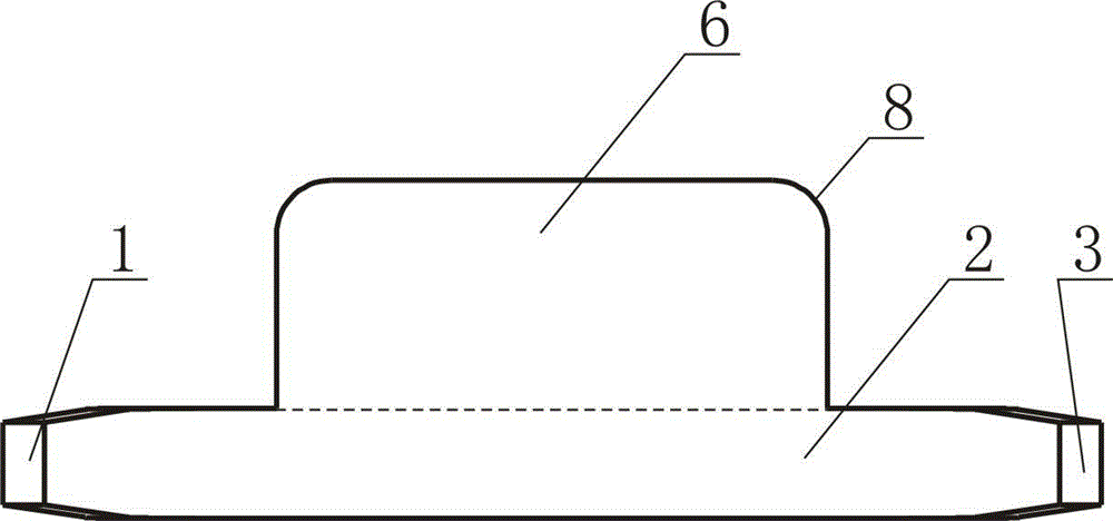
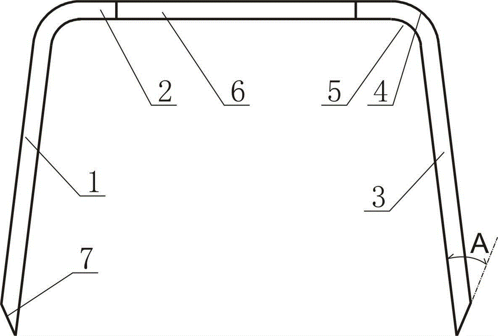
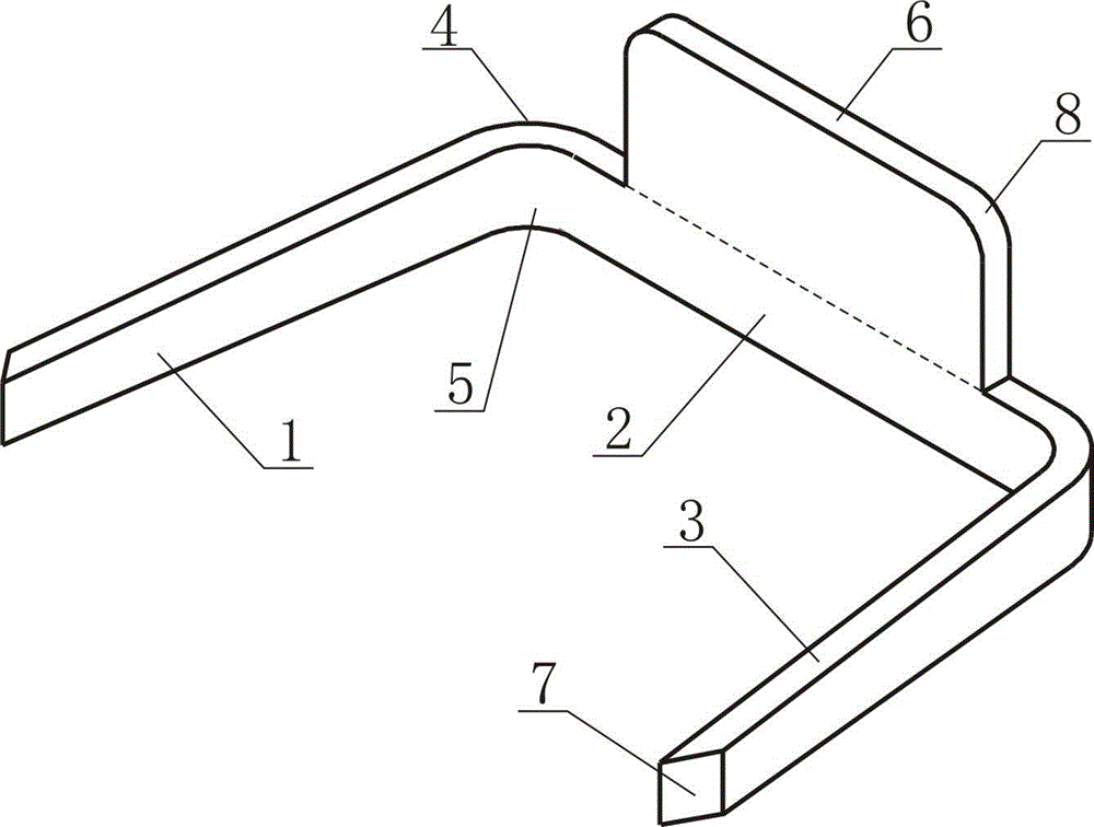
[0029] Such as figure 1 , 2 , shown in 3, a kind of external expansion type medical suture nail that has nail body to help take off plate, comprises rod-shaped nail angle 1, nail beam 2 and rod-shaped nail angle 3, the section of rod-shaped nail angle 1 and nail beam 2 They are all rectangular structures, two rod-shaped nail horns 1 and a nail beam 2 form a "П" structure, and the rod-shaped nail horns 1 and 3 are respectively connected to the outer arcs of the corners of the nail beam 2 The radius of angle 4 is 0.45mm, and the radius of arc angle 5 inside is 0.3mm; The upper side or the lower side are butted, and the front and rear surfaces of the nail...


PUM

PropertyMeasurementUnit
Radiusaaaaaaaaaa
Radiusaaaaaaaaaa
Angleaaaaaaaaaa

Abstract

The invention discloses an external-expansion type medical suturing nail with a nail body falloff promoting plate. The suturing nail comprises rod-shaped nail angles and a nail beam, wherein the cross sections of both the rod-shaped nail angles and the nail beam are of rectangular structures; an n-shaped structure is formed by the two rod-shaped nail angles and the one nail beam, and corners where the rod-shaped nail angles and the nail beam are connected are of arc-shaped structures; the nail body falloff promoting plate is arranged on the nail beam; the side face of the nail body falloff promoting plate is butted with the upper side face or the lower side face of the nail beam; and the front plate surface of the nail body falloff promoting plate is horizontal with the front side face of the nail beam and the rear plate surface of the nail body falloff promoting plate is horizontal with the rear side face of the nail beam. The suturing nail disclosed by the invention, by virtue of the nail body falloff promoting plate, is conducive to the falloff the a nail body; the two rod-shaped nail angles, which are in the form of external expansion, are capable of preventing the nail angles from bending inwards in the process of piercing into skin; and corners on the outer sides of the ends of the two rod-shaped nail angles are cut off, so that the outer sides of the ends of the rod-shaped nail angles are formed as inclined planes, and the two external-expansion rod-shaped nail angles bend inwards when the rod-shaped nail angles are in contact with a nail anvil, so that the success rate of a suturing operation is greatly improved.

Description

technical field [0001] The invention relates to a medical staple, in particular to a staple for circumcision. Background technique [0002] On July 8, 2015, the State Intellectual Property Office published a patent with a publication number of 104758018A and a patent name of a staple. The patent relates to a staple, including a first nail body and a second nail body. The first nail body and the The second nail body is intertwined to form a helical part; the ends of the first nail body and the second nail body located on the same side of the helical part respectively extend in a direction perpendicular to the helical part to form a first nail crown and a second nail crown; The other ends of the first nail body and the second nail body located on the same side of the helix respectively extend at intervals along a direction parallel to the helix to form a first nail leg and a second nail leg. The above-mentioned suturing nail has the characteristics of tight suturing tissue, e...

Claims


Application Information

Patent Timeline
IPC IPC(8): A61B17/326A61B17/064
CPCA61B17/064A61B17/326
Inventor 周明海刘晓鹏张小波黄燕李卫东
Owner JIANG XI YUAN SHENG LANG HE MEDICAL EQUIP
Learn More