
Capacitor counter

A technology of counters and capacitors, which is applied in the field of counting devices and can solve problems such as complex structures

Inactive Publication Date: 2016-02-03
SHANGHAI XUNXI INFORMATION TECH CO LTD
View PDF1 Cites 2 Cited by
  • Summary
  • Abstract
  • Description
  • Claims
  • Application Information

AI Technical Summary

Problems solved by technology

Using this kind of counter can improve the efficiency of counting, but the structure is complicated

Method used


Image

  • Capacitor counter
  • Capacitor counter

Examples


Embodiment Construction

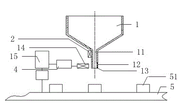
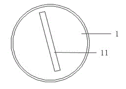
[0013] Such as figure 1 As shown, a capacitance counter of the present invention includes a hopper 1, a vibrator 2, a photoelectric sensor 3, a counter 4 and a conveyor belt 5. Such as figure 2 As shown, the hopper 1 is funnel-shaped, and its bottom is provided with a thin rectangular channel 11, the width of which is adjustable, and the width of the thin rectangular channel 11 is greater than the width of the thin rectangular channel 11 according to the capacitors to be counted during use. A predetermined amount of capacitor thickness, correspondingly, its length is preferably adapted to the size of several capacitors, so that the capacitors can pass through smoothly, prevent being stuck in the channel, and ensure that the number of capacitors passing through at the same time is controlled within Within a range, avoid a large number of capacitors falling out at the same time and cause the counting error of the photoelectric sensor. The hopper 1 is connected to the vibrator...


PUM


Abstract

The invention discloses a capacitor counter. The capacitor counter comprises a hopper (1), a vibrator (2), a photoelectric sensor (3), a counter body (4) and a conveying belt (5). A switch structure is arranged at the bottom of the hopper (1) and controls the capacitors to fall out of a thin rectangular channel (11) of the hopper (1), and fall into material boxes (51) arranged on the conveying belt (5). The hopper (1) is connected with the vibrator (2). The photoelectric sensor (3) is connected with the counter body (4). The controller (15) controls an electromagnet (14), the vibrator (2) and a drive device of the conveying belt (5). The capacitor counter is simple in structure, the capacitors can be accurately measured, and omitting and losing of the capacitors can be effectively prevented.

Description

technical field [0001] The invention relates to a counting device, in particular to a capacitance counter. Background technique [0002] Capacitors are capacitors, and capacitors are one of the most widely used electronic components in the electronic field. Capacitors are small in size. In the packaging process in the production process, manual counting or counting electronic scales are generally used for weighing and counting. A certain number of capacitors are placed in a packaging bag, and then the counted capacitors are packaged and shipped. The manual counting method is inefficient, and it is easy to cause counting errors. Positive errors directly affect the company's benefits, and negative errors will lose the interests of customers. [0003] Chinese patent document CN203410689U discloses a bulk capacitor counting device, which includes a control panel, a material tray, a linear feeder, a conveyor belt, a counting device, a material channel and a material box, and is ...

Claims


Application Information

Patent Timeline
IPC IPC(8): B65B57/20
Inventor 潘根汪梅花
Owner SHANGHAI XUNXI INFORMATION TECH CO LTD
Learn More